6. STEERING SYSTEM
- 92 -
②
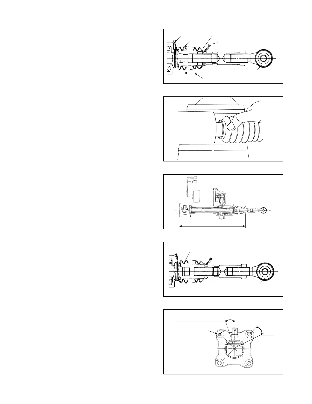
Remove the clamp of the boot connector side.
Shift the position of the boot. Then loosen the
connector lock nut, and remove the connector.
Note: Fix the ball joint to prevent it from turning.
Fig. 6.19
Fig. 6.21
Fig. 6.22
Fig. 6.23
Fig. 6.20
③
Replace the boot with a new one. When
installing the new one, let its end of larger outer
diameter face the actuator.
④
Turn counterclockwise the ball screw till it
contracts the most.
Apply LOCTITE#271 to the threaded areas of
the connector and the lock nut, then install the
connector as specied in Fig. 6.21.
Tightening torque: 176.5 to 215.8 N-m
{18 to 22 kgf-m}
[130 to 159 lbf-ft]
⑤
Clamp the both ends of the boot by wire. Before
clamping, align the position of the joint, as
shown in Fig. 6.23, to correct a dislocation of
the boot.
Push it against
actuator.
BOOT
MASTER HOLE
•
CLAMP
BOOT
LOCK NUT
CLAMP
BALL JOINT
Shift to this position
•
•
512 ± 2 mm [20.16 ± 0.078 in.]
•
BALL JOINT
Breather plug direction
(1 – 2.5 t)
(3.0 – 3.5 t)
20°
20°
 Loading...
