8. LOAD HANDLING SYSTEM
- 146 -
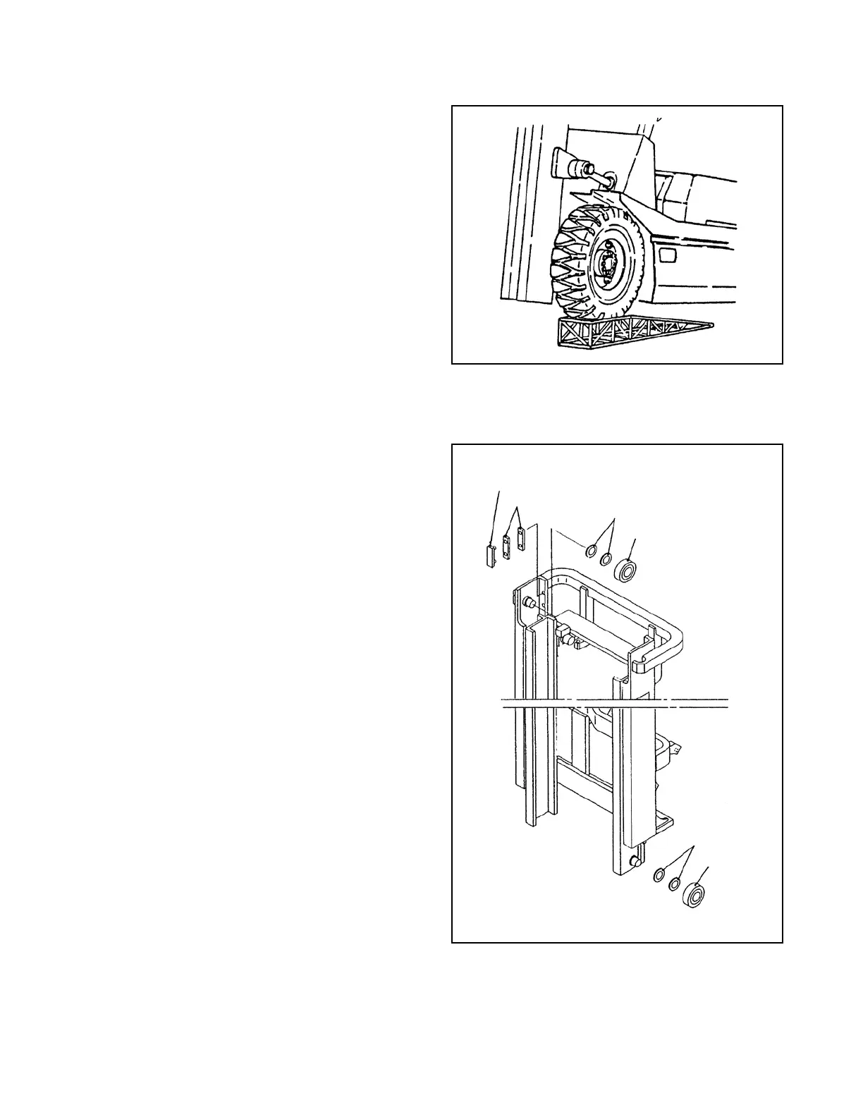
8.2.4 PROCEDURE FOR REPLACING ROLLERS AT MAST SIDE (excluding VM-77X)
(1) Remove the carriage from the inner channel
in the same procedure as described in “8.2.2
PROCEDURE FOR REPLACING ROLLERS
AT CARRIAGE SIDE.”
(2) Move the truck to a level surface and put the
both rear wheels on the bench of 250 – 300 mm
[9.8 – 11.8 in.] in height.
(3) Apply parking brake and block the both rear
wheels securely with blocks.
(4)
Remove the bolt securing the lift cylinder and
inner channel, and hoist the inner channel with a
crane, keeping shims at the end of the piston rod.
(5)
Remove the lift cylinder mounting both at the
lower section of the outer channel and cylinder
support at the middle section, and remove the
lift cylinder from the outer channel. Remove the
hydraulic hose with two wrenches, using caution
not to loosen the ttings at the cylinder side.
(6) Operate the crane to lower the inner channel
gradually and remove the end roller from the
lower section of the inner channel. At the
same time, the end at upper section of the outer
channel can also be removed.
(7) Replacing end rollers
① Remove upper end roller with a puller, keeping
shims.
② Install a new end roller with the shims removed
in step ① . Check for the stamp of S or SS
and install the roller which is marked the same
stamp, pointing the stamp side to the inner
channel side. (See Fig. 8.14.)
③ Replace the lower end roller, using same
procedure as above. In this step, point the stamp
side to the outer channel side.
(8) Operate the crane to hoist the inner channel. Place each roller into the channels.
(9) Install the lift cylinder and carriage in the reverse order of disassembly.
Fig. 8.18
Fig. 8.19
END ROLLER
SLIPPER
SHIM
SHIM
END
ROLLER
SHIM
 Loading...
