ZK300DC SWING GATE OPERATOR USER’S MANUAL
14
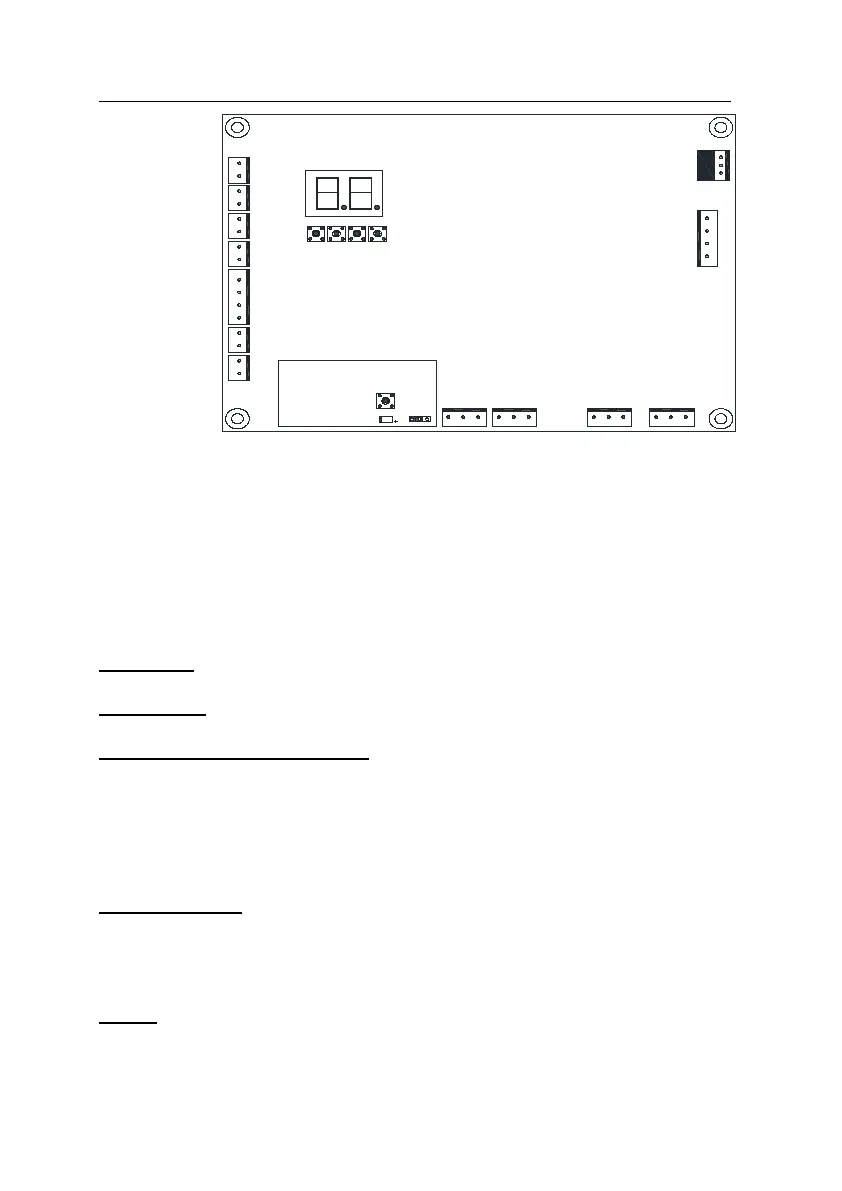
Learn button
Indicator light
C lo se
K1
K2
AC 24V
Jumper
O p e n
Sto p
O p e n/C lose/S to p
Alarm la m p
Electric lock
Motor A Hall
Motor A Hall
Motor B Hall
Motor B Hall
Motor B positive(red)
Motor B negative(black)
Motor A positive(red)
Motor A negative(black)
Pow er +
Infra re d in p u t (N .C.)
Pow er -
BA T+
BA T -
C o m
C o m
C o m
K3
K4
Fig.14 Control board diagram
Electric lock (DC24V)
Connect two wires of electric lock to port ‘Electric lock’.
Flashing light (DC24V)
Attach two wires of flashing light to port ‘Alarm lamp’.
Install the external button switch (Normally open)
The ZK300DC is equipped with an interface for an external button switch or keypad.
To install the keypad attach two wires of your keypad to the port ‘Open/ Close/ Stop’.
The keypad will function in single channel mode.
For three-button switch installation, use the terminals for multi-channel mode. The
port ‘Com’ is the common port, the port ‘Open’ is used to open the gate, ‘Close ’ is
used to close the gate, and ‘Stop’ is used to stop the gate.
Infrared photocell (Normally close)
If the infrared beam is interrupted during closing, the gates will stop immediately.
Connect signal wire of infrared device to ‘Infrared input’ (see Fig.14).
Connect common wire (i.e. ‘power supply –‘) of infrared device to ‘Power -’, connect
‘power supply +’ of infrared device to ‘Power +.
Battery
Connect battery to ‘BAT+’ (red) and ‘BAT-’ (black). A fully charged standard battery still can
provide enough power for operating 10 cycles after power disruption.