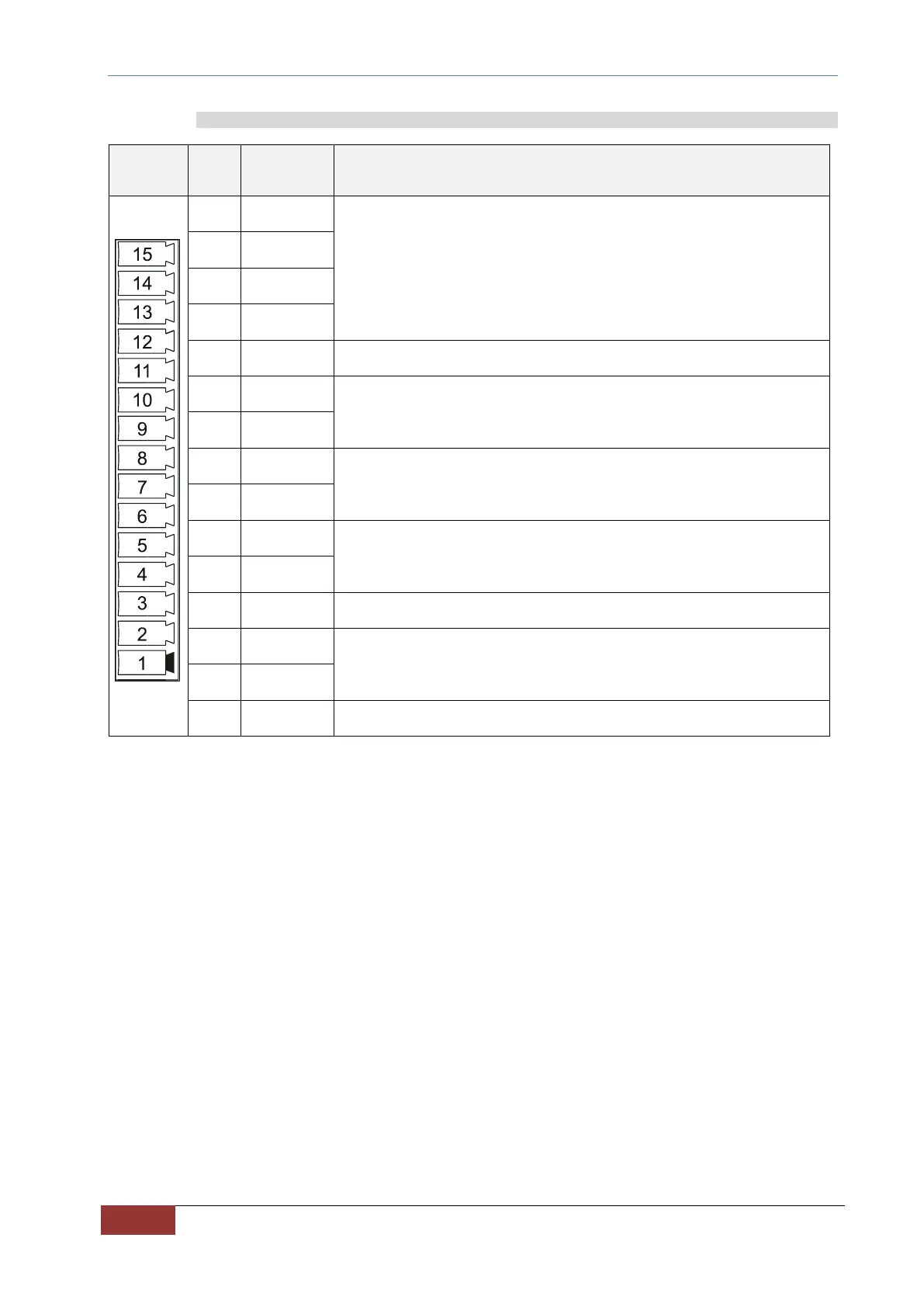
Digital and Analog Logical Connections 7.2.5.1
Configurable logical inputs (see FIG. 18A)
All inputs are optically isolated from the internal regulation.
L.I.C. is the common of the inputs L.I.1, L.I.2, L.I.3, L.I.4.
24Vdc ±10% Imax=10mA
Common of the logical inputs to be connected to the negative of the input
power supply.
Configurable optically isolated logical output (see FIG. 18C)
The transistor is conductive when the output is ON.
Imax = 60 mA @ 30Vdc
Configurable logical output with relay contact.
The contact is normally open.
Imax = 1A @ 30VDC / 0.3A @ 125VAC
Analog Voltage Feedback Input from External 4V0056 (see FIG. 18B).
Input: +/-10V (max. 0.5 mA)
Stabilized power supply - 10mA maximum (ref. PIN 12).
Configurable analog output (see FIG. 18D).
Output: ± 10V /2mA.
TAB. 15 – Connections: Digital and analog I/O