This power supply is equipped withathree conductor power cable. The third conductor is the ground
conductor. When the cable is plugged-in to an appropriate receptacle, the power supply is grounded.
Under no circumstances should this power supply be operated without an adequate ground
connection. Ifatwo contact receptacle is encountered, it must be replaced byathree contact
receptacle, properly grounded. This operation should be done byaqualified electrician. It is
recommended to keep the AC input wires separate from the DC output and signal wires to avoid
interference.
To meet radiated EMI specification, the EMI suppressor clamp should be attached to the AC cable as
close as possible to theAC inlet of the power supply.
WARNING
WARNING
Some components inside the power supply are at AC voltage even when the
On/Off switch is in the “Off” position. To avoid the hazard of electric shock,
disconnect line cord and load and wait2minutes before removing cover.
Turn off the AC input power before making or changing any rear panel connection.
Make sure that all connections are securely tightened before applying power.
There isapotential shock hazard when usingapower supply witharated output greater than 40V.
Use load wiring withaminimum insulation rating equivalent to the maximum output voltage of the
power supply.
3.7 CONNECTING THE LOAD
3.7.1 Selecting wire size
Two factors must be considered in selecting wire size.
1. Wires should be at least heavy enough to avoid overheating while carrying the power supply load
current at the rated load, or the current that would flow in the event the load wire were shorted,
whichever is greater.
2. Wire size should be selected to enable voltage drop per lead to be less than 0.5V at the rated current.
It is recommended to minimize voltage drop on the wires to prevent excessive output power
consumption from the power supply.
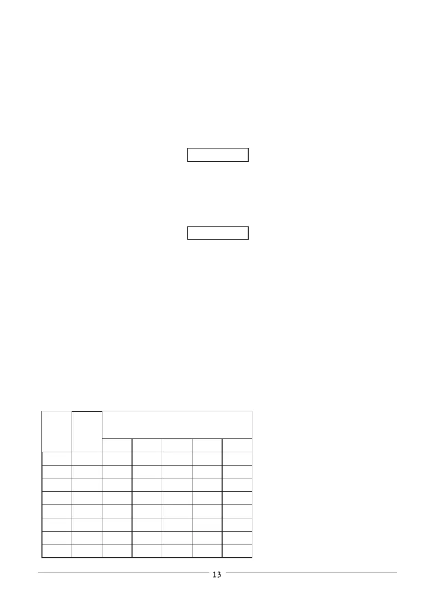
Please refer to Tables 3-1 and 3-2 for maximum wire length to limit voltage drop by American and
European measurements respectively.
Table 3-1: Maximum wire length for
0.5V drop on lead (in feet)
wire size
AWG
5A
40 20 10 41
63 31 15 6 1.7
100 50 25 10 3
160 80 40 16 5
253 126 63 25 8
400 200 100 40 13
640 320 160 64 21
1016 508 254 102 34
14
12
10
8
6
4
2
0
2.526
1.589
0.9994
0.6285
0.3953
0.2486
0.1564
0.0983
Maximum length in feet -
to limit voltage drop to 0.5V or less
10A 20A 50A 150A
Resistivity
Ohm/kft