K
Kevin McdonaldAug 17, 2025
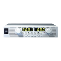
What to do if TDK-Lambda GENESYS GEN 2400W has no output and all displays are blank?
- MMargaret MitchellAug 17, 2025
If your TDK-Lambda Power Supply shows no output and the displays are blank, check if the AC power cord is defective and replace it if necessary. Also, verify that the AC input voltage is within the correct range and connect to an appropriate voltage source.