83-517-000 Rev. A
8.3 ISOLATED PROGRAMMING & MONITORING CONNECTOR
Refer to Table 8-1 for a detailed description of the rear panel Isolated Programming & Monitoring connector. To
provide the lowest noise performance, it is recommended to use shielded-twisted pair wiring.
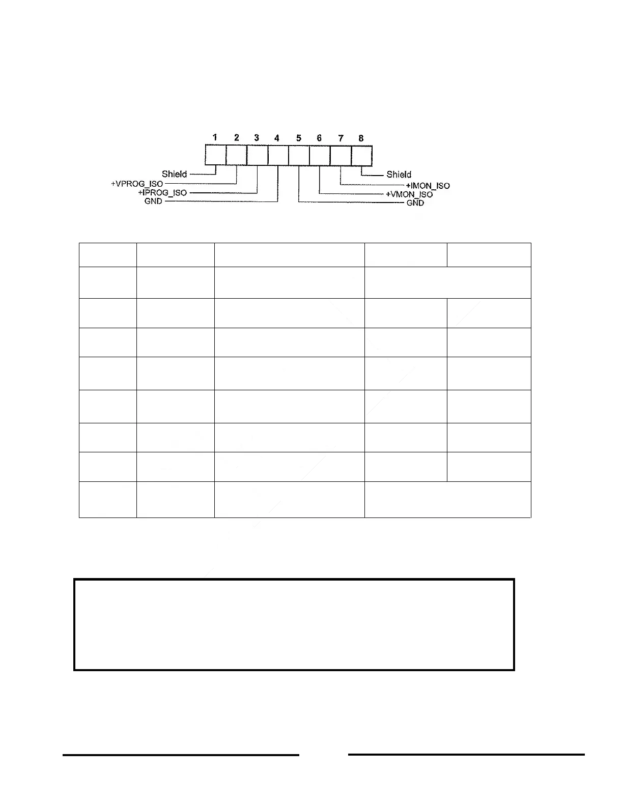
Refer to Figure 8-1 for a description of the Isolated Analog Programming & Monitoring connector.
Isolated Analog Programming Plug P/N: MC1.5/8-ST-3.81, Phoenix.
Figure 8-1: Isolated Programming and Monitoring Connector
Shield, connected internally to
chassis of the supply.
Output Voltage programming
input
Output Current programming
input
Ground for programming
signals.
Ground for programming
signals.
Output voltage monitoring
output
Output current monitoring
output
Shield, connected internally to
chassis of the supply.
Table 8-1: Description of Isolated programming & Monitoring Connector
CAUTION
When the Isolated Analog Option is installed, DO NOT apply any signals to the non-isolated
VPGM and IPGM (J1-9 and J1-10) pins. All other J1 features may be used normally. Refer to
Section 4.5 for a description of J1 features.
Parallel Operation: The optional Isolated Analog (IS510/IS420) Interface must be installed in
both the Master and Slave unit.