83-517-000 Rev. A
4.3 REAR PANEL
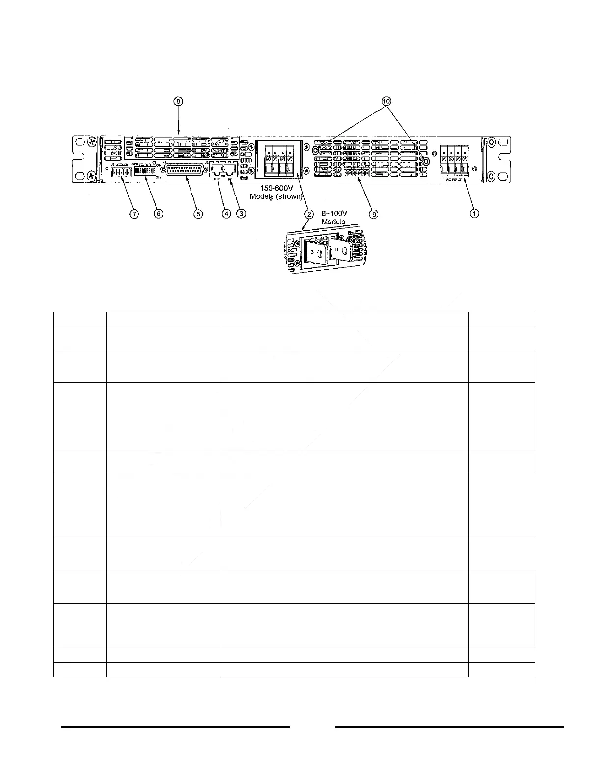
See Figure 4-2 to review the connections and controls located on the power supply rear panel. Refer to Table 4-
2 for explanations about the rear panel connections and controls.
Figure 4-2: Rear Panel Connections and Controls
Table 4-2: Rear Panel Connections and Controls
Header with a screw plug connector (Phoenix Contact
P/N PC6-16/4-GF-10,16)
Bus-bars for 8V to 100V models.
Wire clamp connector for 150V to 600V models (shown
in Figure 4-2).
RJ-45 type connector, used for connecting power
supplies to RS-232 or RS-485 port of computer for
remote control purposes. When using several power
supplies in a power system, the first unit Remote-In is
connected to the computer and the remaining units are
daisy-chained, Remote-In to Remote-Out.
RJ-45 type connector, used for daisy-chaining power
supplies to form a serial communication bus.
Programming and
Monitoring connector
Connector for Remote Analog interface. Includes Output
voltage and Output current limit programming and
monitoring signals, Shut-off (SO) control (electrical
signal), Enable/Disable control (dry-contact), Power
Supply OK (PS_OK) signal and operation mode (CV/CC)
signal.
Nine position DIP-switch for selecting Remote
Programming and Monitoring modes for Output voltage,
Output current and other control functions.
Connector for making remote sensing connections to the
load for regulation of the load voltage and compensation
of load wire voltage drop.
Blank sub-plate for standard units (shown). LAN
connector for LAN Interface option, IEEE connector for
IEEE option, USB for USB Interface option and Isolated
Analog connector for Isolated Analog Interface option.
M4 stud and hardware for chassis ground connection.