83-517-000 Rev. A
CAUTION
To maintain the isolation of the power supply and to prevent ground loops, use an
Isolated programming source when operating the power supply via Remote Analog
programming at the J1 connector.
6.4 REMOTE VOLTAGE PROGRAMMING OF OUTPUT VOLTAGE AND
OUTPUT CURRENT
Perform the following procedure to set the power supply to Remote Voltage programming:
1. Press the power supply AC Input ON/OFF power switch to the OFF position.
2. Set DIP-switch SW1-1 to the UP position for Output voltage external programming and SW1-2 to the UP
position for output current limit external programming.
3. Set SW1-3 to select the programming voltage range according to Table 6-3.
4. Ensure that SW1-7 and -8 are set to the DOWN (default) position.
5. Connect a wire jumper between J1-8 and J1-12 (refer to Table 4-4).
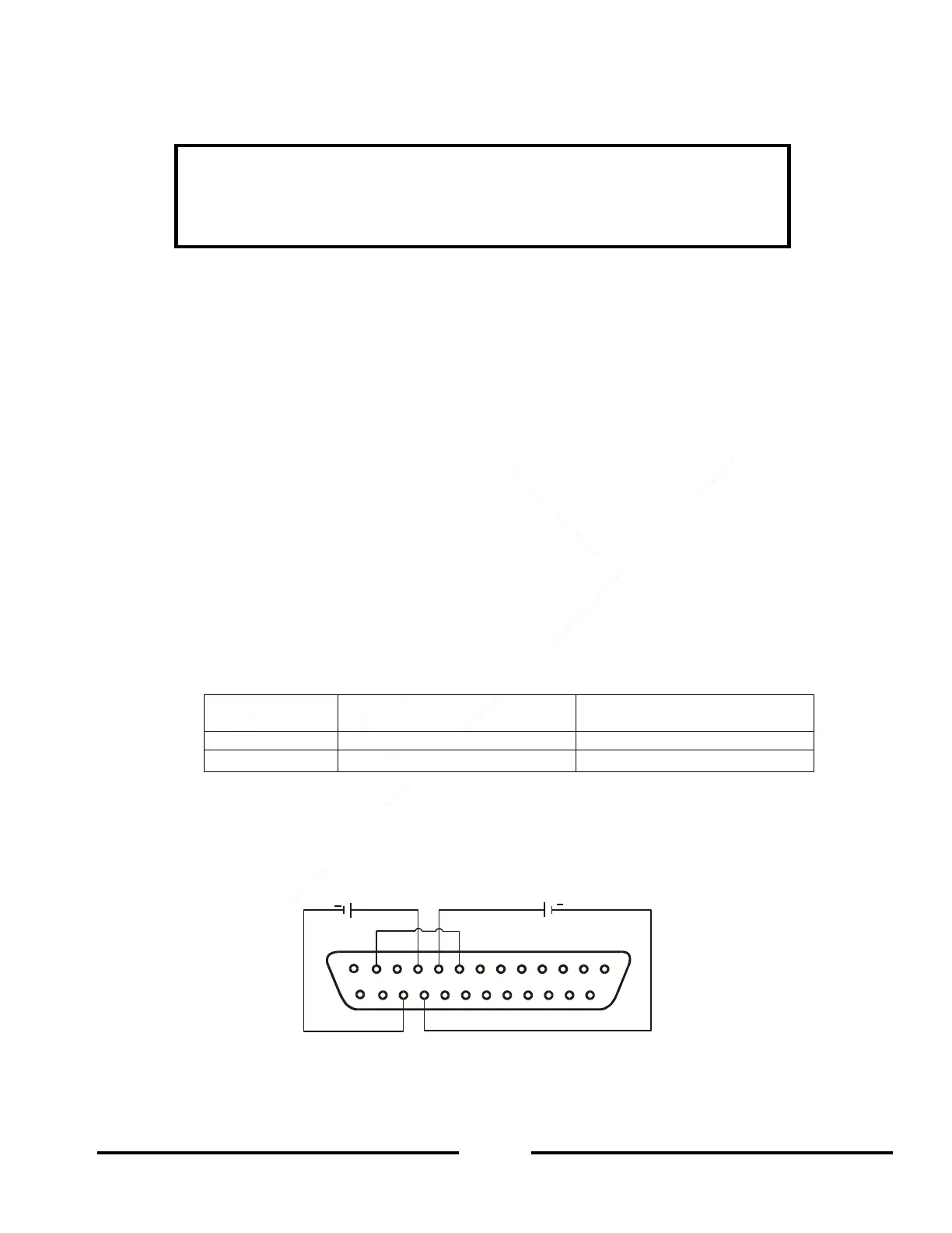
6. Connect the programming source to the mating plug of J1 as shown in Figure 6-1. Observe correct
polarity for the voltage source.
7. Set the programming sources to the desired levels.
8. Press the power supply AC Input ON/OFF power switch to the ON position.
9. Press the OUT button to turn the power supply ON.
10. Adjust the programming sources to change the power supply Output voltage and Output current.
NOTES:
SW1-4, -5, -6 and -9 are not required for Remote Analog V/I programming. Their settings can be determined
according to the application.
The control circuits allow the user to set the Output voltage and Output current limit up to 5% over the
model-rated maximum value. The power supply will operate within the extended range, however it is not
recommended to operate the power supply over its Output voltage and Output current rating, and
performance is not guaranteed.
Output Voltage programming
VPGM (J1-9)
Output Current programming
IPGM (J1-10)
Table 6-3: SW1-3 Setting and Programming Range
iFigure 6-1: Remote Voltage Programming Connection
1
14
13
25
1012
8
9
23 22
+
+
CURRENT LIMIT
PROGRAMMING
OUTPUT VOLTAGE
PROGRAMMING
J1 connector, rear panel view
Fig.6-1: Remote voltage programming connection