83-517-000 Rev. A
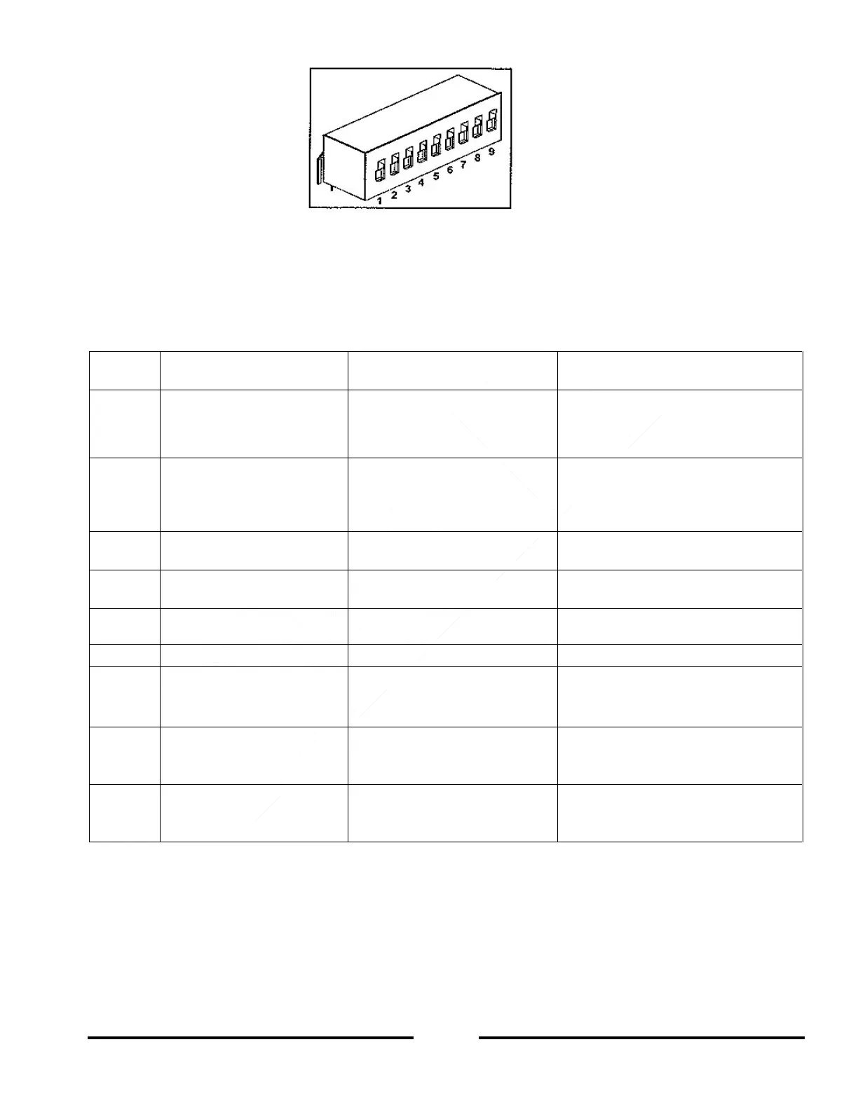
Figure 4-4: SW1 Setup DIP-switch
SW1 DIP-Switch Position Function 4.4.1
Refer to Table 4-3 for descriptions of SW1 position functions. The factory default setting is DOWN for all
DIP-switch positions.
Table 4-4: SW1 DIP-switch Position Functions
Output Voltage
Remote Analog
Programming
Output Voltage
Programmed by Front Panel
Output Voltage
Programmed by Remote Analog
External Voltage or External
Resistor
Output Current Limit
Remote Analog
programming
Output Current Limit
Programmed by Front Panel
Output Current Limit
programmed by Remote Analog
External Voltage or External
Resistor
Programming Range Select
(Remote Voltage/Resistive)
Output Voltage and
Current Monitoring Range
Shut-Off (SO) Logic select
ON: High (2-15V) or Open
OFF: Low (0-0.6V) or Short
ON: Low (0-0.6V) or Short
OFF: High (2-15V) or Open
Output Voltage
Resistive Programming
Output Voltage
programmed by
External Voltage
Output Voltage
programmed by
External Resistor
Output Current Limit
Resistive Programming
Output Current Limit
programmed by
External Voltage
Output Current Limit
programmed by
External Resistor
Rear panel
Enable/Disable control
is not Active
Rear panel
Enable/Disable control
is Active
Resetting the SW1 DIP-switch 4.4.2
Before making any changes to the SW1 DIP-switch settings, disable the power supply output by pressing the
front panel OUT button. Ensure that the Output Voltage falls to zero and the OUT LED is off. Then use any small
flat-blade screwdriver to change the SW1 DIP-switch settings.