83-517-000 Rev. A
Auxiliary Power Supply 4.3.1
There are two Auxiliary Outputs provided:
o +5VDC Output: maximum Output current is 0.2ADC
o +15VDC Output: maximum Output current is 0.2ADC
Both Auxiliary outputs are considered a limited power source.
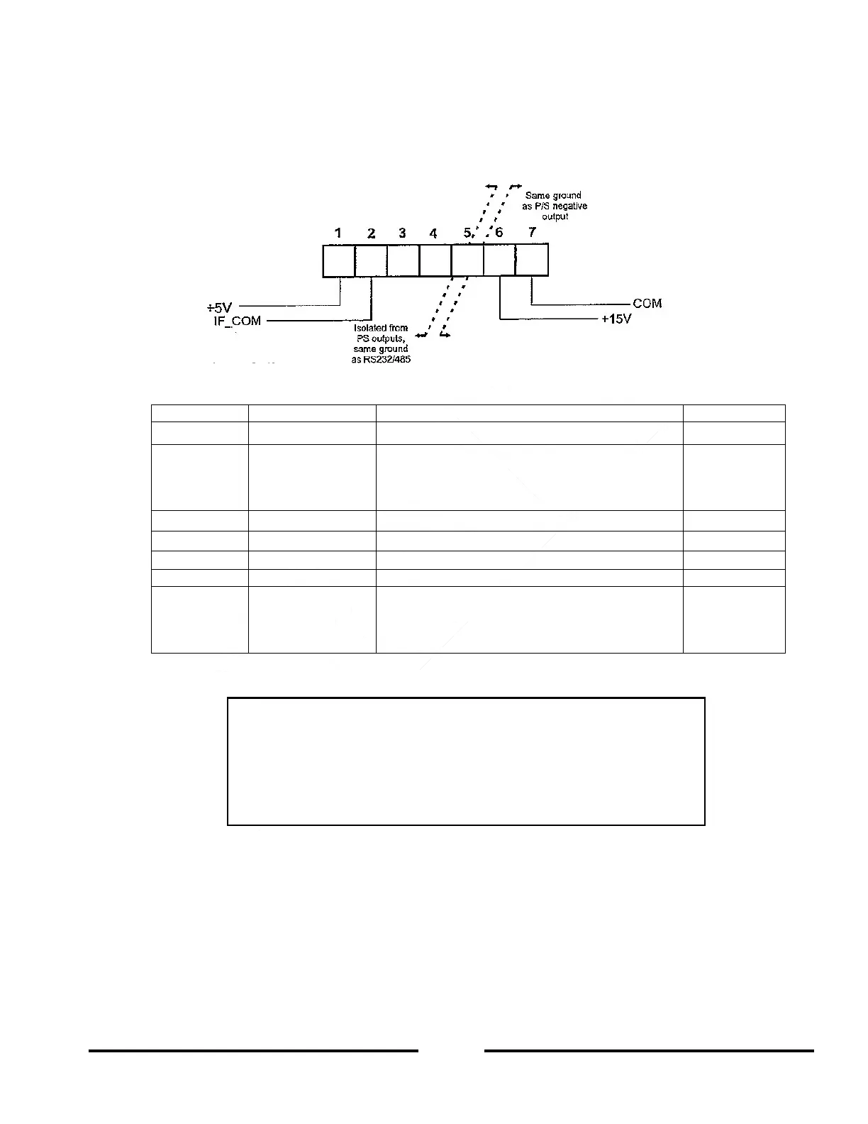
Figure 4-3 Connector Detail (Auxiliary Output)
+5.0V +/- 5%, max current = 0.2A
Isolated Interface Common. Return for the
Aux +5VDC, SO, ENA control, PS_OK signal
and for the RS-232/RS-485, LAN, IEEE and
USB interfaces
+15V +/- 5%, max current = 0.2A
Control Common. Return for the Aux
+15VDC, VMON, IMON, CV/CC, LOC/REM.
Referenced internally to the negative output (-
V) potential.
Table 4-3: Auxiliary Power Connector Function Description
4.4 REAR PANEL SW1 SETUP SWITCH
The SW1 Setup switch (see Figure 4-3) is a 9-position DIP-switch that allows the user to choose the following:
Internal or Remote programming for Output voltage and Output current limit.
Remote voltage or resistive programming of Output voltage and Output current Limit.
Select range of Remote voltage and resistive programming.
Select range of Output voltage and Output current monitoring.
Select the Remote Shut-Off (SO) control logic.
Select between RS-232 and RS-485 serial communication interface.
Enable or disable the rear panel Enable/Disable control (dry contact).
CAUTION
The COM terminal (Pin 7) is referenced internally to the –V potential
(and J1 Pin 12) of the power supply. Do not attempt to bias any of these
terminals relative to the –V or any other potential. Use the Isolated
Programming interface option to allow control from a programming
source at a different potential.