J7Ol
TxUOMx:
!
(50
YEL GRY
56)
V-4RX
ONLY
V-2RX
ONLY
JOINT
PCB
ASSY
910
4
cit
ee
oe
“R703
A7OUV74W)
:
é
4
7
aS
We
la)
pene
1.
2.
NOTES
=
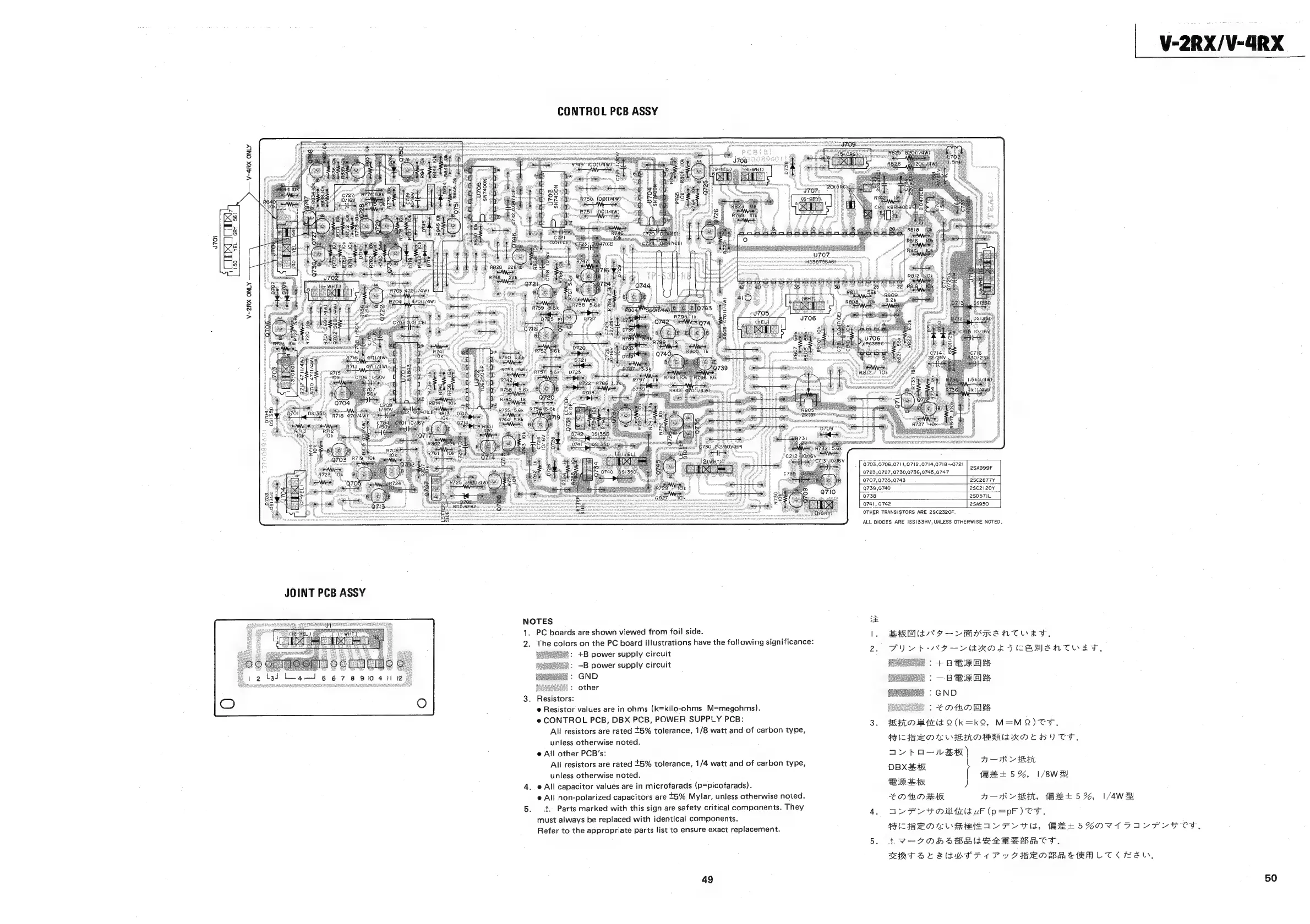
CONTROL
PCB
ASSY
Q703,Q706,Q711,Q712,Q714,Q718~Q721
Q723
,Q727,0730,Q736,Q745,0747
2SA999F
Q707,Q735,0743
28C2877Y
Q739,Q740
28C2120Y
Q738
2S057IL
Q741,
Q742
2SA950
OTHER
TRANSISTORS
ARE
2SC2320F.
ALL
DIODES
ARE
1SS!I33HV,
UNLESS
OTHERWISE
NOTED.
PC
boards
are
shown
viewed
from
foil
side.
I.
The
colors
on
the
PC
board
illustrations
have
the
following
significance:
+B
power
supply
circuit
—B
power
supply
circuit
GND
other
Resistors:
@
Resistor
values
are
in
ohms
(k=kilo-ohms
M=megohms).
e
CONTROL
PCB,
DBX
PCB,
POWER
SUPPLY
PCB:
All
resistors
are
rated
5%
tolerance,
1/8
watt
and
of
carbon
type,
unless
otherwise
noted.
@
All
other
PCB’s:
All
resistors
are
rated
5%
tolerance,
1/4
watt
and
of
carbon
type,
unless
otherwise
noted.
@
All
capacitor
values
are
in
microfarads
(p=picofarads).
e@
All
non-polarized
capacitors
are
t5%
Mylar,
unless
otherwise
noted.
4,
Parts
marked
with
this
sign
are
safety
critical
components.
They
must
always
be
replaced
with
identical
components.
Refer
to
the
appropriate
parts
list
to
ensure
exact
replacement.
49
BRED
NY
-—VMASREANTOETF.,
PY
vb
NG—VERNE
FVICBBMANTOET,
+BB
RAK
—-BS
kaw
GND
EOD
El
FRILO
Bhzlt
Q(k
=kQ,
M=MQ)
TT,
PSILFSE
DS
GRE
ORRI
RON
CH)
TST.
a>
FoR
Amy
HT
oe
(H+
5%,
1/8WH!
a
=
>
u
ERR
:
eS
Oth
EAR
ARLE,
HL
5%,
1/4w
Al
AL
FY
YOM
firld
uF
(p=pF)
CF.
FRIIS
E
OC
MME
IAL
TU
lS,
METS
MONVADAY
FLTC,
LV-7OHh>RRSRSBSBACT,
RRS
SC
RSWSF
TFT
1
Py
FIEND
SERBLTK
KAY,
V-2RX/V-4RX
50