Do you have a question about the Teac V-5010 and is the answer not in the manual?
Procedures for adjusting tape speed, wow and flutter, and reel torque.
Key precautions before performing electrical adjustments, including cleaning and demagnetization.
Diagrams showing specific locations for adjustment points on the main PCB.
Procedures for checking and calibrating playback performance metrics.
Procedures for checking monitor performance, including input level and frequency response.
Procedures for checking recording performance, including bias, level, and distortion.
Detailed breakdown of external components with reference numbers and part numbers.
Detailed breakdown of internal components with reference numbers and part numbers.
Detailed breakdown of mechanism components with reference numbers and part numbers.
Detailed breakdown of parts specific to V-7010/V-7010B models.
Detailed breakdown of parts specific to the V-5010 model.
Schematic and component layout for the Main Printed Circuit Board.
Schematic and component layout for the Control Printed Circuit Board.
Schematic and component layout for the Jack Printed Circuit Board.
Schematic and component layout for the Trans Printed Circuit Board.
Schematic and component layout for the Phone Printed Circuit Board.
Schematic and component layout for the Oscillator Printed Circuit Board.
| Brand | Teac |
|---|---|
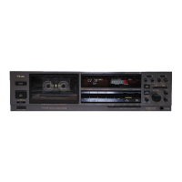
| Model | V-5010 |
| Category | Cassette Player |
| Language | English |