8
Gas Connection
continued
NOTICE:
A FIRE EXTINGUISHER FOR CLASS A, B,
C & D FIRES SHOULD BE READILY AVAILABLE AT
ALL TIMES.
WARNING:
THE VENTILATION/ACCESS OPENINGS
FOR THE TANK, IN THE REAR AND LOWER FRONT
OF THE CABINET, MUST BE FREE AND CLEAR FROM
DEBRIS. THE GAS MUST BE TURNED OFF AT THE
SUPPLY CYLINDER WHEN THE GRILL IS NOT IN USE.
Be sure to set the gas cylinder upright so the Cylinder
Valve is at the top. This will ensure proper vapor
withdrawal.
Procedure for 20 lb Tank Connection: (See
Figures 6, 7, 8)
1. In order to make sure the Cylinder Valve is fully
closed, turn the Handwheel clockwise until it stops.
2. Turn all Burner Output Knobs to OFF.
3. Move the grill to a level, open area and engage the
Base Brake to limit rolling. (See Figure 15, Page 13)
4. Place the gas cylinder in the space provided in the
base and secure the tank with the tank strap latch
assembly. (See Figure 7 or 8 ) Remove the
protective caps from Cylinder Valve Outlet and
Nipple, as necessary.
5. Inspect the Coupling Nut, Nipple, Cylinder Valve
Outlet and Cylinder Valve for any damage, dirt or
debris. Remove dirt or debris. Replace any damaged
parts with TEC-specified replacement parts or parts
approved by your Gas Cylinder Supplier.
6. Inspect Regulator and Hose Assembly for any
damage, dirt or debris. Remove dirt or debris.
Replace any damaged parts prior to use.
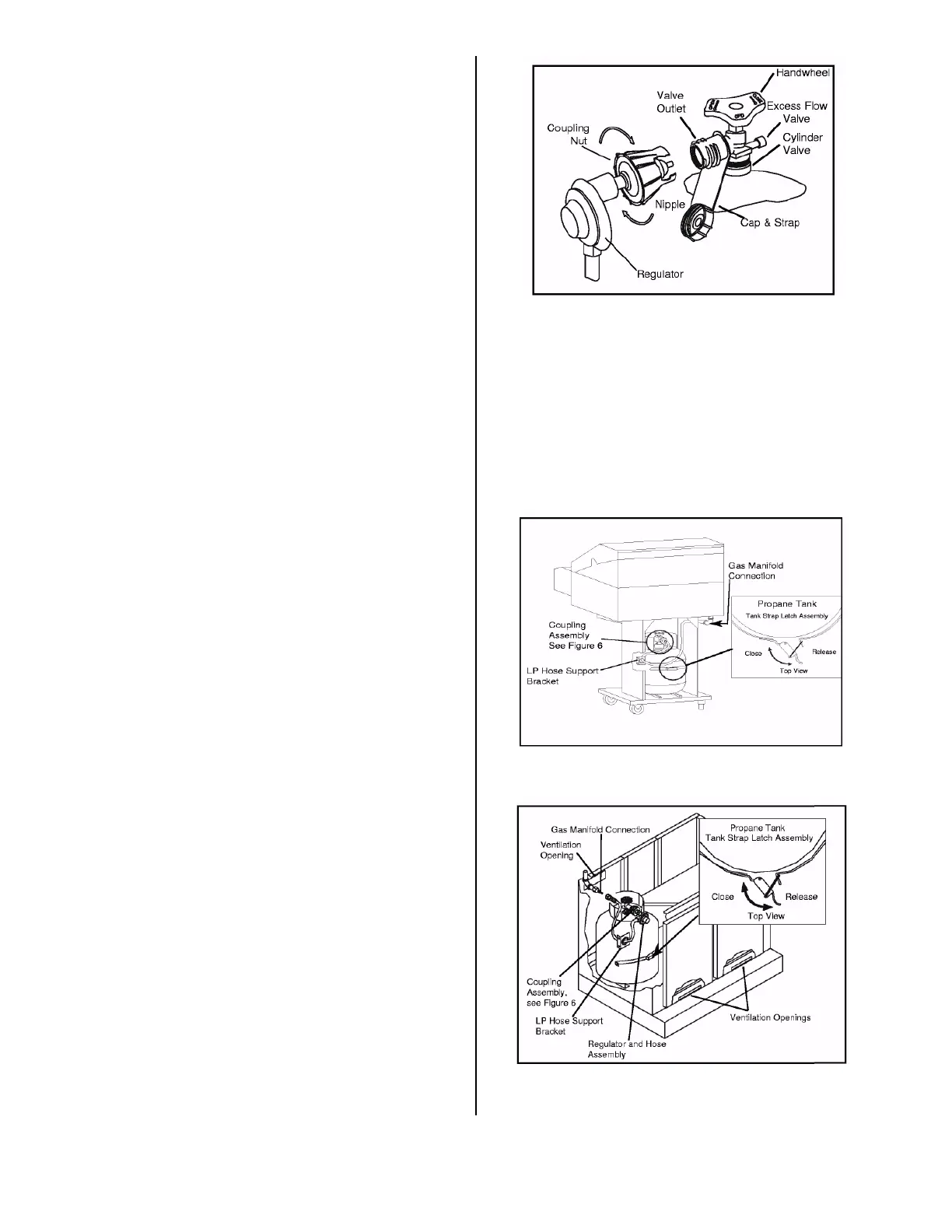
7. With the Regulator in your hand, insert the Nipple
into the Cylinder Valve. Make sure the Nipple is
centered in the Cylinder Valve Outlet. Tighten the
Coupling Nut by hand, making sure not to cross-
thread the connection. Please note that when you
connect your cylinder to the grill, you will feel the
nipple seal when there is slight resistance. (See
Figure 6) Turn until the Coupling Nut will turn no
further (about one-half to three-quarters of a turn) to
complete the connection. Tighten only by hand; do
not use tools. If you cannot complete the final
connection, disconnect the Coupling Nut and repeat
step 7, above. If you are still unable to complete the
connection, replace the appropriate parts.
8. (CABINET MODELS) With the Regulator Hose in
your hand, place the hose through the hole in the
front of the LP Hose Support Bracket, avoiding all
contact with the drip tray. Then attach Quick
Disconnect Fitting to the Gas Manifold Connection
using the Quick Disconnect Instructions on page 10.
Figure 6. REGULATOR AND HOSE / COUPLING
ASSEMBLY
9. (PEDESTAL MODELS) With the Regulator Hose
in your hand, place the hose through the back-side of
the LP Hose Support Bracket avoiding all contact
with the drip tray. Then place the hose through the
hole in the right side of the Pedestal Body and attach
the Quick Disconnect Fitting to the Gas Manifold
Connection using Quick Disconnect instructions on
page 10.
Figure 7. Gas Tank Placement-Sterling II FR
Pedestal
Figure 8. Gas Tank Placement-Sterling and
Sterling G-Series Cabinet