6
Installation
continued
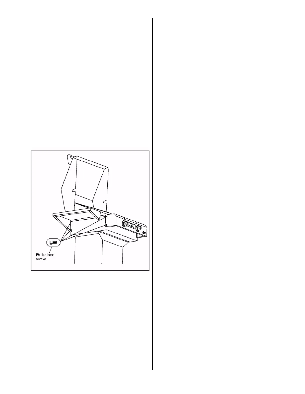
Side Shelf Installation (Sterling FR only)
Note: Our one (1) Side Shelf Vinyl Grill Cover is
designed for grills with the Side Shelf Mounted on the
left.
1. Remove the Side Shelf from the box.
2. Remove the protective coating from the Side Shelf.
3. Using a #2 Phillips-head Screwdriver loosen and
remove the upper two (2) Phillips-head Screws from
the left or right side of the Grill Housing.
(See Figure 5)
4. Loosen the lower two (2) Phillips-head Screws of
the left or right side of the Grill Housing.
Do not remove the screws.
5. Mount the Side Shelf on the loosened lower screws.
6. Insert two (2) Phillips-head screws into the upper
holes and tighten.
7. Tighten the lower screws.
Figure 5. Side Shelf Assembly (Sterling II FR
shown)
Assembly
Once the grill has been mounted on the appropriate base,
unpack the Radiant Glass Panels, the Cooking Grids, the
Burner Output Knobs and the Warming Rack and place
in their proper locations following the instructions.
Assembly
continued
Radiant Glass Panels
1. Remove the Radiant Glass Panels from the
packaging material. The Panels are located in the
Prepack Box.
2. Place a Radiant Glass Panel with the smooth side up
onto the four support brackets directly above each
burner assembly. (See Figure 16, Page 16 or set up
sheet included with grill) If the glass is not level it
will be necessary to make a slight adjustment to the
brackets with a pair of pliers so that the glass sits
level on all four brackets.
Cooking Grids and Warming
Rack
1. Remove the Cooking Grids and Warming Rack from
the packaging material. Peel off any protective
adhesive coating from the Warming Rack. Wash the
Cooking Grids and Warming Rack in warm soapy water.
2. Set the Cooking Grids in place with the closed side
of the channels facing up, on top of the Radiant
Glass Panels. Set the Warming Rack in place on top
of the Hood Body Rear Trim Panel. (See Figures 16
& 18, Page 16 or set up sheet included with grill)
Burner Output Knobs
(Sterling FR)
1. Remove the Burner Output Knobs from the
packaging material. (see Figure 10 & 11, Page 10 or
set up sheet included with grill)
2. With the "OFF" indicator at the top, slide the Knob
fully onto the valve stem ensuring each knob is
centered in the surrounding bezel. Remove knob and
adjust bezel as necessary.
Burner Output Knobs
(Sterling G-Series FR)
1. Remove the Burner Output Knobs from the
packaging material. (see Figure 10 & 11, Page 10 )
2. Using a 5/64" Allen wrench (supplied), loosen the
set screw in the bottom of each knob, enough to
allow mounting onto the valve stems. Do not
remove the knob insert.
3. With the "OFF" indicator at the top, slide the Knob
fully onto the valve stem ensuring each knob is
centered in the surrounding bezel. Remove knob and
adjust bezel as necessary.
4. Turn the Knob counterclockwise to LOW and, while
continuously pushing the Knob firmly onto the valve
stem, tighten the set screw using the 5/64" Allen wrench.
THEN TURN THE KNOB CLOCKWISE TO "OFF"