11
Operation
continued
Burner Ignition With Match
If your spark ignition system is not working properly, the
burners may be ignited manually, using a match.
CAUTION:
DO NOT HOLD A MATCH IN YOUR HAND
ABOVE A BURNER WHEN LIGHTING THE BURNER
MANUALLY. PLACE A MATCH IN THE ALLIGATOR
CLIP AT THE END OF THE MATCH HOLDER. LIGHT
THE MATCH, THEN PLACE THE LIT MATCH NEAR
THE BURNER TO BE LIT AS DESCRIBED BELOW.
Procedure:
1. If ignition does not occur in 10 seconds, turn the
Burner Output Knob to OFF, wait 5 minutes, and
repeat the lighting procedure.
2. Open the grill hood and ensure all Burner Output
Knobs are in the "OFF" position and that there is
nothing on top of the Cooking Grids.
3. For LP gas, open the Gas Cylinder Valve by turning
the handwheel counter-clockwise.
(see Figure 6, Page 8)
For Natural gas, open the Gas Valve in the main
line.
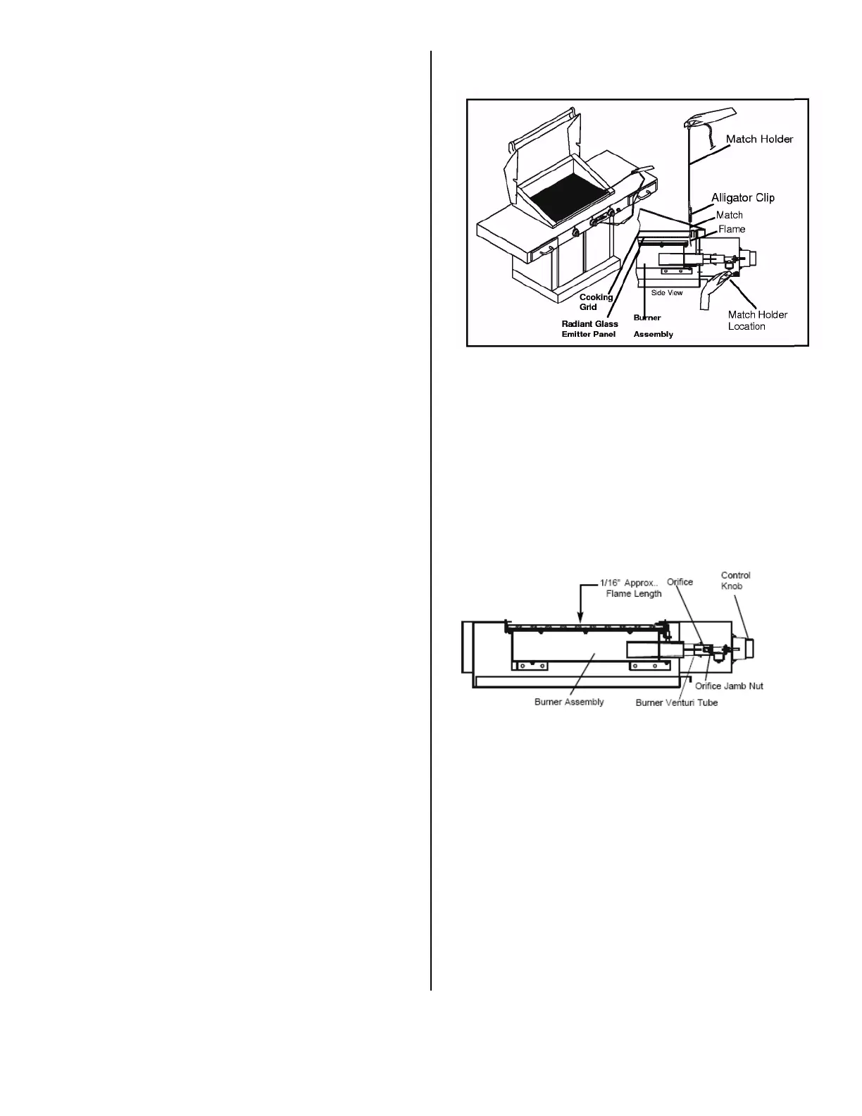
4. Remove the match holder from the lower ledge of
the grill front backside. (See Figure 12, Page 11).
5. See Figure 12, Page 11 for match lighting approach.
To prepare, place a match in the alligator clip at the
end of the match holder. Then, place the alligator
clip end of the match holder close to the cooking
surface and light the match. While observing that the
match remains lit, insert the burning match between
the Radiant Glass Panel and the front inner wall of
the grill downward to the level of the burner top.
Turn the Burner Output Knob to HIGH for burner
ignition.
6. Repeat this procedure for each burner to be lit.
7. Operate and adjust the burner as described in Step 5
of the Burner Ignition and Operation Procedures on
Page 10.
8. To extinguish the flame, depress and rotate the
Burner Output Knobs to OFF.
Figure 12. Match Lighting (Sterling G-3000 FR
Shown)
Burner Flame
The burner flame should be approximately 1/16" tall and
present a blue or orange glow when the burner is in
operation. (See Figure 13, Page 11)
WARNING:
EACH GAS ORIFICE MUST BE
PROPERLY LOCATED ON THE ORIFICE BRACKET,
ATTACHED TO THE VENTURI ON THE BURNER
ASSEMBLY. AN IMPROPERLY LOCATED ORIFICE
CAN LEAD TO BODILY INJURY AND PROPERTY
DAMAGE. THE PROPER LOCATION IS SHOWN IN
FIGURE 13.
Figure 13. Burner Flame and Orifice Location,
Shown without Cooking Grid and Radiant Glass
Panel (side view)
Low Heat Adjustment
The burner's low heat output is preset at the factory. To
adjust this setting, follow the instructions below.
WARNING:
NEVER ADJUST A BURNER SO LOW
THAT IT MAY GO OUT DURING USE. DO NOT
OPERATE GRILL WITH DISENGAGED LOW HEAT
ADJUSTMENT SCREW.
The Low Heat Adjustment Screw only applies to the
burner operation at the LOW setting. Any efforts to
make adjustments at another setting will go unnoticed
until the burner is turned to LOW, where it may