Po si zio na re le co lon ne all’e stre mi tà
del le tra ver se (pos. 5-6, Fig.39) se
-
guen do la nu me ra zio ne e lo sche ma
del la fi gu ra 39.
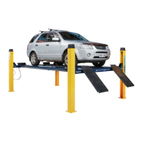
In fi la re dall’al to del le co lon ne le aste
di si cu rez za (12) fa cen do le pas sa re
tra la par te po ste rio re del le tra ver se
(5-6) ed i per ni di gui da (13) come in
fi gu ra 43.
Ve ri fi ca re che le aste di si cu rez za
sia no di rit te.
Mon ta re le aste di si cu rez za con I
bor di ar ro ton da ti del le aso le ver
-
so la par te fron ta le del le co lon ne.
Fig.43 Sede di in se ri men to dell’asta
di si cu rez za
Bloc ca re quin di l’e stre mi tà in fe rio re del le aste (12) con le viti TE
M10x25 (30) e le ro set te Ø10x30 (29) come mo stra to in fi gu ra 44.
To glie re i dadi M20 (pos.25, Fig.42) e le ro set te Ø21x37(26) dall’e -
stre mi tà del le funi e in se ri re i ter mi na li (19) del le stes se ne gli ap po -
si ti fori del le pia stre su pe rio ri del le co lon ne.
Fig.42: av vi ta re sui ter mi na li (19) i dadi (25) e le ro set te (26). Du -
ran te que sta ope ra zio ne é im por tan te ve ri fi ca re che i sen so ri (17)
sia no cor ret ta men te po si zio na ti sul le funi (18) fi gu ra 45.
Fig.44 Bloc cag gio dell’a sta di si cu rez za
Fig.44 Sa fe ty rod loc king
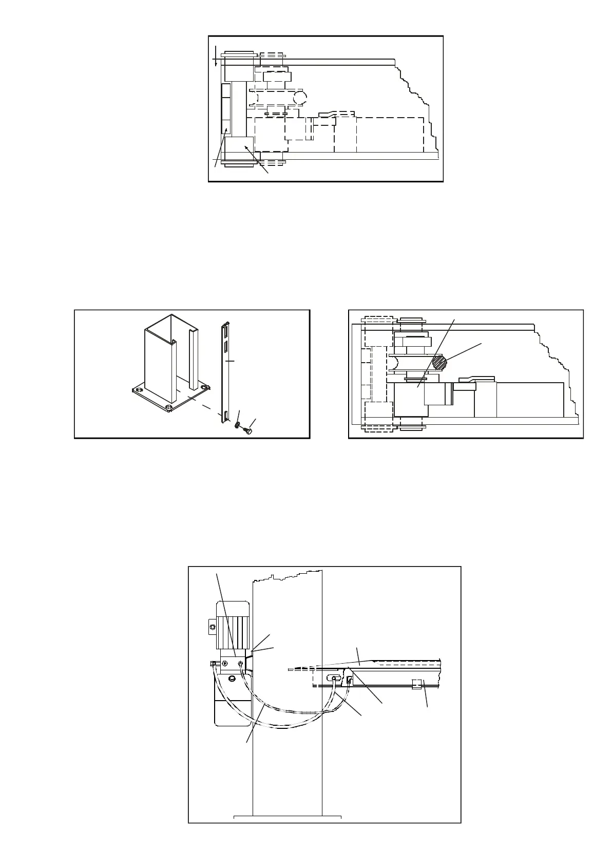
ALLACCIAMENTO IMPIANTO IDRAULICO
Fig.46: col le ga re il tubo in gom ma alta pres sio ne (20) al rac cor do
del tubo me tal li co sul la pe da na fis sa (7) ser ran do lo a fon do. To -
glie re il tap po (21) dal cor po del la cen tra li na (10), av vi ta re il rac cor -
do (22) e in se ri re nel lo stes so il tubo di sfia to (23) pre ce den te men
-
te col le ga to al rac cor do po sto sul fon del lo del ci lin dro di sol le va
-
men to (24).
Fig.46 Al lac cia men to im pian to
idrau li co
Position the posts at the end of the
cross- pieces (pos. 5-6, fig.39) obser
-
ving the numbering and the lay- out
shown in figure 39.
Fit the safety rods (12) from the top of
the posts, inserting them between the
rear face of the cross- pieces (5-6)
and the guide pins (13) as shown in
figure 43.
Check the Safety rods are straight.
Fit the Safety rods with the rounded
edges of the slots towards the front
of the posts.
Fig.43
Housing for fitting safety rod
Now secure the bottom end of the rods (12) using M10 x 25 H.H.
screws (30) and the 10 x 30 washers (29) as shown in figure 44.
Remove the M20 nuts (pos.25, fig.42) and the 21 x 37 washers (26)
from the ends of the lifting cables and install the terminal blocks (19)
in the relevant holes on the top plates of the posts.
Fig. 42: screw the nuts (25) and washers (26) onto the terminal
blocks (19). During this procedure make sure that the sensors (17)
are correctly positioned on the lifting cables (18) as shown in figure
45.
Fig.45 Po si zio na men to dei sen so ri fune
Fig.45 Positioning of lifting cable sensors
HYDRAULIC SYSTEM CONNECTION
Fig.46: connect high pressure rubber hose (20) to the union of the
metal pipe on the fixed platform (7) and tighten it fully down. Remove
the plug (21) from the body of the hydraulic power unit (10),
screw in union (22) in its place, and fit the breather pipe (23) that
was previously connected to the union on the bottom of the lift
cylinder (24).
Fig.46
Hydraulic system
27
12 13
5-6
12
29
30
14
18
10
21
22
20
23
7
24
22
 Loading...