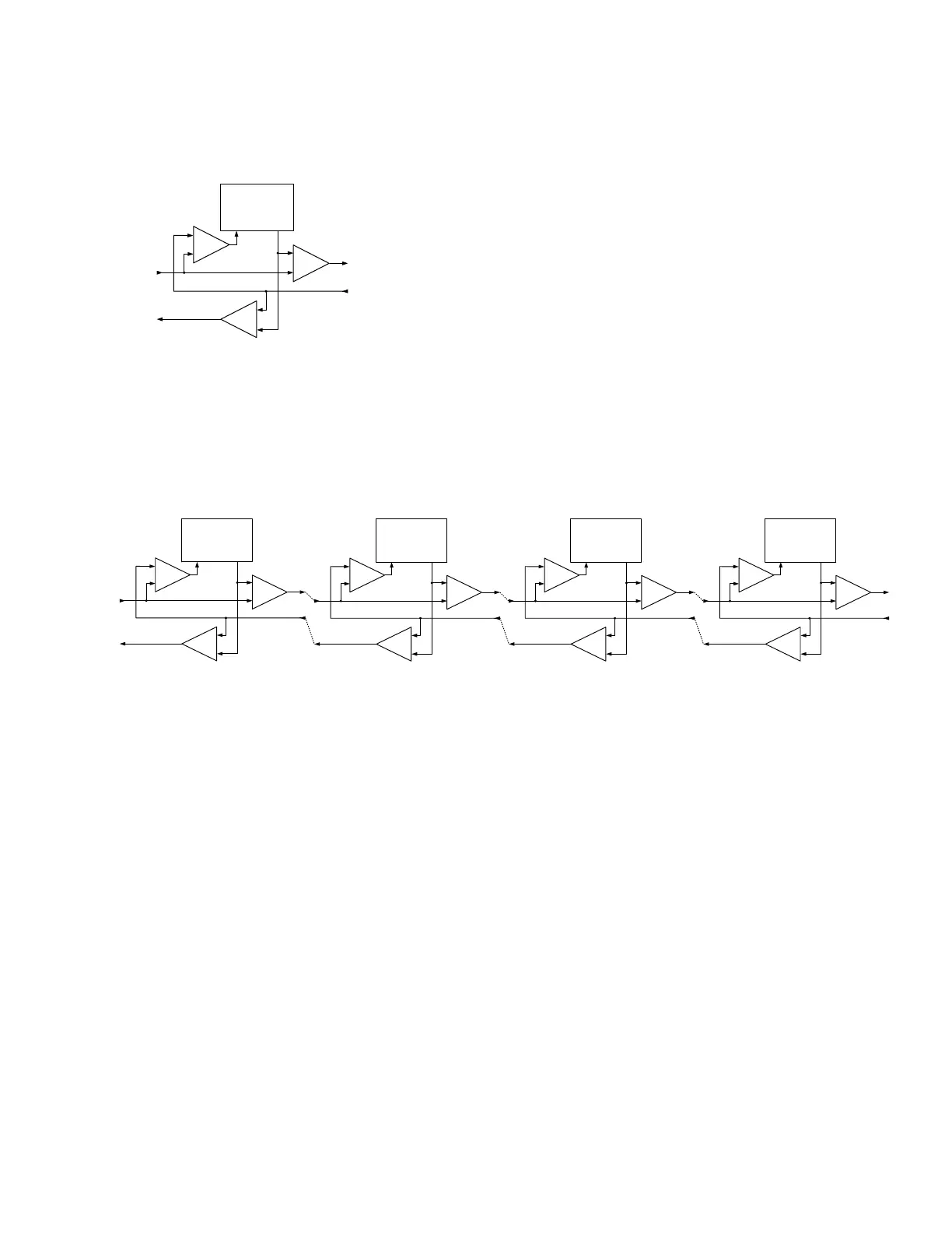
The box marked "THIS BLOCK" defines the function of this Building Block. A "BLOCK"
represents a functional component which is a CI part # and may have an "INPUT", or an
"OUTPUT", or both.
The SUMers, shown below, are part of every Block, and support the CI SERIES Interface. Each
Summer Mixes the Buss Audio signals with the local Audio Signals and Routes them based on
the installer configuration.
The Buss structure allows "Blocks" to be "Added" to form a "Chain. A chain is formed by
plugging a Master output into a Slave input of another unit.
Most system requirements are satisfied with a single "Chain", Very large system may have
several "Chains", defined as Groups, Groups may be joined together by a Hub, such as the
CI-ODC-4
Jumpers inside of each unit or Block allow the installer to select what comes in from the BUSS
and what goes out to the Buss. Please see the individual Installation Guide for each product for
more information about jumper selections and settings of each electronic component.
Automatic Level Control and Limiting is used to achieve the standard Output signal levels to
keep the sound quality consistent throughout a system.
The Call Pair is a "Party Line" passing through to all the Blocks forming a Group
The Operator Console Responds to a Switch Closure by initiating a Calling Sequence
All Switches must be floating, or isolated with Opto-Couplers
The Alert Pair is a "Party Line" passing through to all the Blocks forming a Group
The Operator Console sends a signal to all the Other Blocks, such as my Microphone is On
The other Blocks may be configured to "Respond" in an appropriate manner
Responder Blocks, are electrically isolated, with Opto-couplers
A CI-BUSS system is made up of a chain of functional blocks of products each designed to do a
special job or function.