10/29/2019 Tech Works CI-Series Systems Planning & Installation Manual Page 3 of 42
Figures
CI-ODC-1 Operator Desk Console 4 & 29
CI-ODC-4 Operator Desk Console 4 & 33
CI-HSI-41 Headset Interface 5 & 20
CI-MSI-22 Microphone Speaker Interface 5 & 24
FS-ODC - Operator Foot Switch 6
FS-1-PLUS – Procedure Room Foot Switch 6
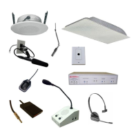
CS-520 - Dual-Muff, Noise Cancelling Headset 6
CS-540 - Convertible Headset 6
PRO-42 - Boundary Microphone 6
PRO-45 Hanging Microphone 6
MJ-1 - Microphone Jack 7
PRO-SGM - Shotgun Microphone Assembly 7
PRO-ODM - Operator Desk Microphone 7
HM-1 Omni-Directional Hidden Microphone 7
System 2 Wall Mount Speaker 7
System 21 Round Ceiling Mount Speaker 7
System 5 Ceiling Speaker 7
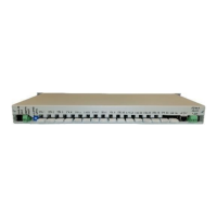
PA-402 Paging and Program Amplifier 8
PA-SI-1 Paging and Program Speaker Interface 8
PMI-B - Portable Music Interface 8
CAT6-BB - RJ-45 Cable Breakout Board 9
CAT6-* Patch Cord 9
PS-2437A - 24VDC @3.7A Power Supply 9
PC-* Power Patch Cable 9
CI-BUSS Connector 11
System Functional Block Diagram 12
PA-BUSS Connector 13
PA-BUSS Chain 13
Selective Gain Reduction, “Ducking” 15
Master Slave Connection Diagram 16 & 39
Automatic Level Control, ALC 17
Typical System Wiring Diagram 36-38
Packaging and Mechanical 39
CI-BUSS Crossover wiring 40