10/29/2019 Tech Works CI-Series Systems Planning & Installation Manual Page 40 of 42
Installation Best Practices and Frequently Asked Questions:
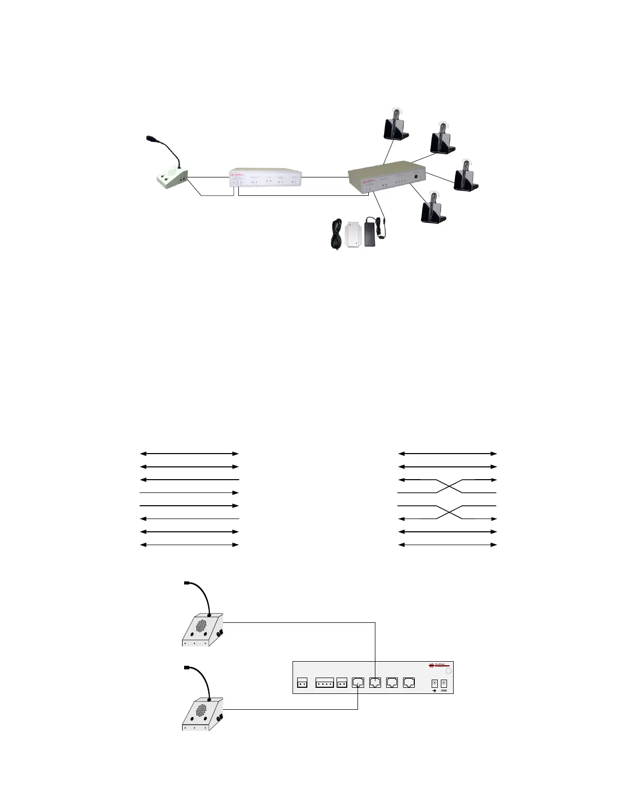
Always connect the Collaborative Intercom active components from Master to Slave on the
CI-BUSS.
By placing the CI-MSI-22 in the middle of the system it can act as an audio router for who hears
who.
By placing the Power Supply on the last device in the chain you can back feed the entire system
using standard Power Cords. To add more headsets just add another CI-HSI-41 to the one shown
and move the power supply to the new unit. Expansion of up to, no more than, 6 units, on the CI-
Buss will give the best performance.
If you absolutely have to have 2 Operator Desk Console on one CI-MSI-22 you can use a
crossover cable and connect the second ODC to the “CI-Master” Connector
“MASTER” CONNECTOR
“SLAVE” CONNECTOR
CALL_SW_(+) (1)
CALL_SW_(-) (2)
ALERT_IN_(+) (7)
ALERT_IN_(-) (8)
MASTER_OUT_(+) (4)
MASTER_OUT_(-) (5)
MASTER_IN_(+) (3)
MASTER_IN_(-) (6)
(1) CALL_SW_(+)
(2) CALL_SW_(-)
(7) ALERT_OUT_(+)
(4) SLAVE_IN_(+)
(5) SLAVE_IN_(-)
(3) SLAVE_OUT_(+)
(6) SLAVE_OUT_(-)
(8) ALERT_OUT_(-)
NORMAL CI-BUSS: RJ-45 Cable wired 1 to 1; Ethernet Standard Wiring
Signal Pairing: (1,2) Control; (3,6) Audio; (4,5) Audio; (7,8) Control
TIA 568B COLOR
WHITE OF ORANGE
ORANGE
WHITE OF GREEN
BLUE
WHITE OF BLUE
GREEN
WHITE OF BROWN
BROWN
“MASTER” CONNECTOR
CALL_SW_(+) (1)
CALL_SW_(-) (2)
ALERT_IN_(+) (7)
ALERT_IN_(-) (8)
MASTER_OUT_(+) (4)
MASTER_OUT_(-) (5)
MASTER_IN_(+) (3)
MASTER_IN_(-) (6)
CI-BUSS: RJ-45 Cable wired CROSS-OVER Wiring
TIA 568B COLOR
WHITE OF ORANGE
ORANGE
WHITE OF GREEN
BLUE
WHITE OF BLUE
GREEN
WHITE OF BROWN
BROWN
“MASTER” CONNECTOR
CALL_SW_(+) (1)
CALL_SW_(-) (2)
ALERT_IN_(+) (7)
ALERT_IN_(-) (8)
MASTER_OUT_(+) (4)
MASTER_OUT_(-) (5)
MASTER_IN_(+) (3)
MASTER_IN_(-) (6)