GB
13
6 - ACCESSORIES
6.1 - WATER CONNECTION HOSES
• Length 1 m, insulated, female:
- Ø 3/4” code 70600054 for CHG 8,
-
Ø 1” code
70600055 Z for CHG 1
1, CHG 15
and CHG 17.
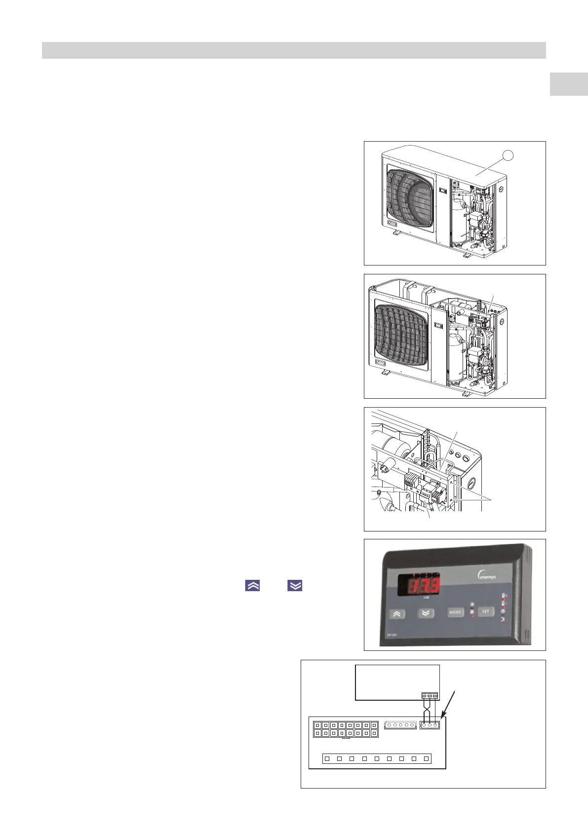
6.2 - SINGLE START-UP KIT (for single-phase model)
• Code 70550004.
• This kit is used to lower the start-up current of the single-phase
compressors. The average RMS current during the start-up phase is
approximately 44
A for the
CHG 8 (single-phase).
• After having removed the side panel, also remove the upper panel
A.
• The starter is located on the back on the electric panel and is secured by
two screws and two nuts (supplied).
Note:
To facilitate the installation process, it is preferable to connect the
wires between the starter and the compressor contactor before
securing the starter to the panel.
• Disconnect the black wire and the blue wire from terminals 4 and 6 of the
compressor contactor and connect them to the starter (blue wire on
terminal 2 and black wire on terminal 4).
•
Connect the wires (supplied) between the starter and the compressor
contactor:
- blue wire on terminal 1 of the starter and on terminal 6 of the
compressor contactor,
- black wire on terminal 3 of the starter and on terminal 4 of the
compressor contactor
.
6.3 - REMOTE CONTROL
• Code 70250055.
• The functions and display are exactly the same as those on controller.
• The only difference concerns the buttons and which are
separated by the “
ON/OFF” and “Mode” buttons.
• Reminder: the parameters are accessed by simultaneously pressing the
“
ON/OFF” and “Mode” buttons.
•
The controller is designed to be installed inside sheltered rooms.
• Connection:
- the control is delivered with a connecting it to the
“ECH” controller
,
-
to extend the link, max. length: 100 meters, use
twisted pair shielded cable with a cross section of at
least 0.5 mm
2
(shielding of the ground on unit side).
CAUTION:
Do not route this cable near power cables.
The operation must take performed with the unit's
power supply off and locked out.
CONN A
CONN B
SERIAL KEYB
24 25 26
Starter location
Starter
Starter
mounts
Compressor contactor
Back of “ECH” controller
REMOTE
CONTROL
Connector:
blue wire = terminal 24
red wire = terminal 25
black wire
= terminal 26
 Loading...