GB
5
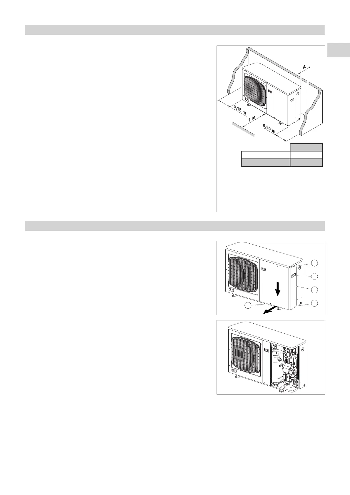
3 - INSTALLATION
• Protection index of the unit: IP 24.
• Select the location for the unit on the basis of the following criteria:
-
the unit must be installed outside,
- the unit must not be installed near the following:
.
sources of heat,
. combustible materials,
.
return/air intake of an adjacent building.
- it is necessary to make sure that the free space around the unit is
provided (see the minimum dimensions on the drawing opposite),
-
installation must be simple and make maintenance work easy,
- the unit must be fixed on a hard base and must be protected from risks
of flooding,
- use the anti-vibration mountings supplied, making sure that they are not
compressed too much when the fastening screws are tightened,
- the blown air must not be directed towards surrounding windows,
-
vibrations and noise must not be transmitted to a nearby building,
- avoid:
. excessive exposure to salty air or sulphuric gas,
. the proximity of the extractor fan,
. projections of mud (next to a roadway or path, for example),
. areas where there is strong wind blowing against the unit's air
exhaust.
4 - CONNECTIONS
4.1 - DISASSEMBLY
• To remove side panel A:
- remove the 3 retaining screws
B,
- lower the panel
(1) using the handle C,
- pull the lower part of the panel toward you
(2).
4.2 - HYDRAULIC CONNECTION
•
Connect the water pipes to the corresponding connections. See Ø and position on page 4.
• Install the hydraulic filter (supplied) on the water intake. Connect it using 2 isolation valves for cleaning purposes.
•
Install a shut-off valve if a fill/drainage connection is used.
NOTE:
"Water connection hose" accessories may be used (refer to the accessories paragraph).
CHG 8 0.15
CHG 11/15/17 0.25
* This dimension does not acccount for the
installation of the hydraulic filter with two
shut-off valves positioned behind the unit:
provide 0.30 m.