GB
6
4.3 - ELECTRICAL CONNECTION
4.3.1 - GENERALITIES:
• The acceptable voltage variation is: ± 10% during operation.
•
The electrical connection conduits must be fixed.
• Use the cable clamps at the rear of the unit and route the wires under the electric panel, at the level of the terminal strips.
• Class 1 unit.
• The electrical installation must comply with the standards and regulations applicable where the unit is being installed (in
particular NF C 15-100
IEC 364).
4.3.2 - POWER SUPPLY
• The power supply must come from an isolation and electric protection device (not supplied) in accordance with existing
regulations.
•
The installation must be protected by a
double-pole circuit-breaker (not included). See the intensity ratings table
below.
Note:
The unit is designed to be connected to a power supply having a TT neutral regime (neutral to ground) or TN.S regime
(to neutral) as per NF C 15-100.
POWER SUPPLY CABLE
•
Section 230V/1/50Hz
: 3 G 4 mm
2
.
• Section 400V/3N/50Hz : 5 G 2.5 mm
2
for CHG 8, CHG 11, CHG 15 and 5 G 4 mm
2
for CHG 17.
• The sections are given as an indication only. They have to be verified and adapted, if necessary, according to the
installation conditions and the standards in force.
• Make the electrical connections to the terminal board as per the electrical diagram.
CURRENT
CAUTION:
In the case of a three-phase power supply, prior to commissioning the unit, make sure that the phase rotation
order is correct. If the rotation order is not respected, the compressor will turn backwards (and make an
abnormal noise). To fix this, simply invert the 2 phases.
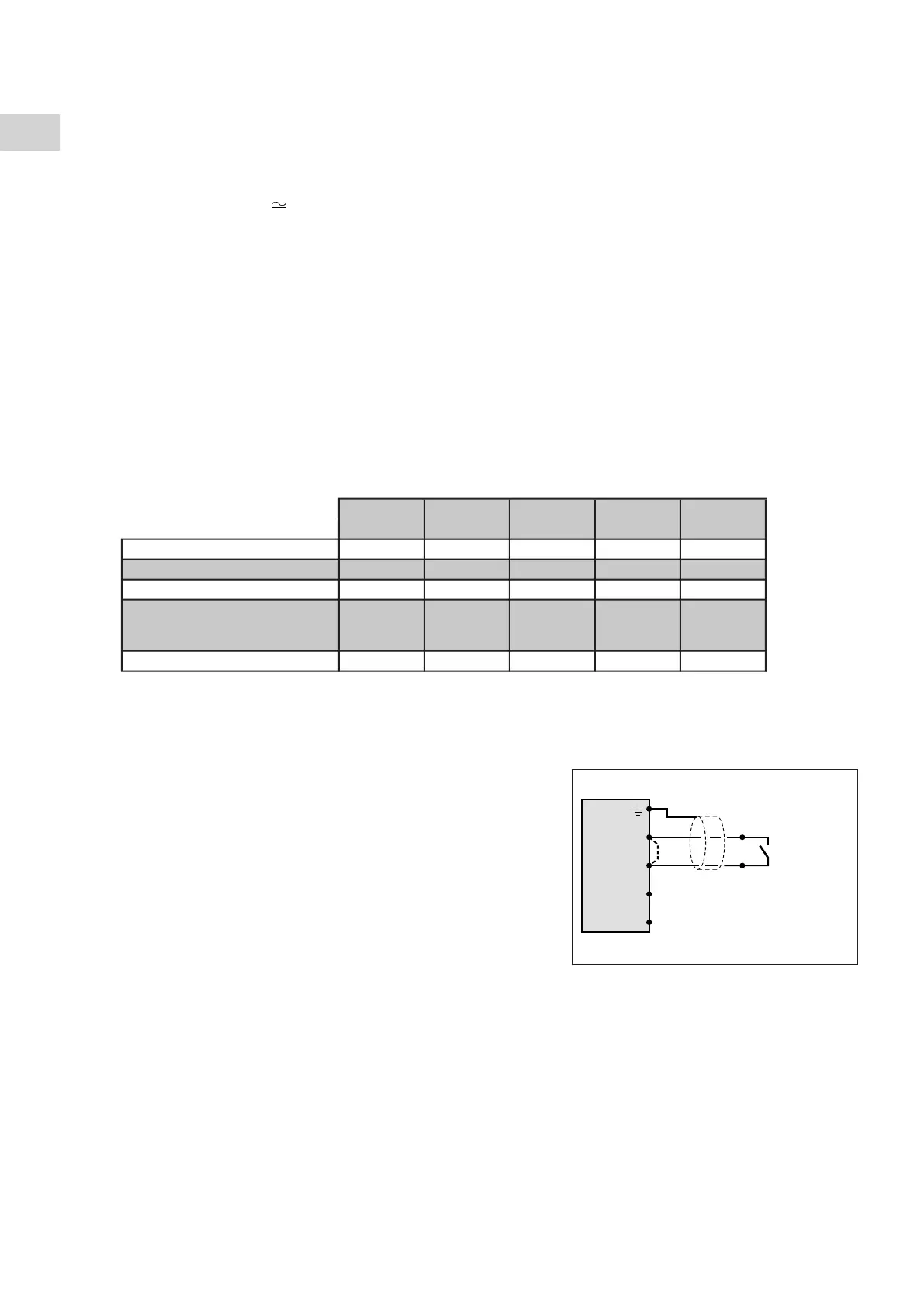
4.3.3 - CONTROL BY EXTERNAL CONTACT
• The unit can be controlled remotely by connecting a good-quality,
potential-free external contact (not supplied) for the remove
On/Standby signal (contact closed = operation authorized, contact
open = in stand-by mode).
• The On/Stand-by signal is connected to terminals 1 and 2 of the PCB
located in the switch box (remove the existing bridge - see diagram).
• The wiring of these contacts must not be routed near power cables in
order to avoid electromagnetic disturbances.
• Use shielded cable with twisted pair (shielding grounded on generator
side).
• Max. connection cable length: 100 m.
• Minimum wire size: 0.5 mm
2
.
4.3.4 - REMOTE CONTROL
•
See paragraph "accessories".
4.3.5 - MISCELLANEOUS
•
Alarm transfer:
Potential-free changeover contact (2A - 250 VAC max.) available on the unit's terminal strip (terminals 5 (common), 6
and 7 of the printed circuit) for remote signaling. See schematic.
- In case of alarm:
- contact open between terminals 5 and 6,
- contact closed between terminals 5 and 7.
CHG 8 CHG 8 CHG 11 CHG 15 CHG 17
230/1/50 400/3N/50 400/3N/50 400/3N/50 400/3N/50
Nominal current A 15.2 7.2 10 11.2 13.7
Max. current A 23 9 12 14 17
Starting current A 97 48 64 74 101
Start-up current with
single-phase start-up kit
Protection rating A 25 12 16 16 20
On/Stand-by
(k) Jumper to be removed
(
k)