EasyManuals Logo

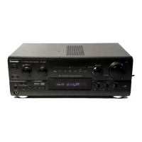
Technics QUARTZ SA-GX100 User Manual

Technics QUARTZ SA-GX100
33 pages
To Next Page IconTo Next Page
To Previous Page IconTo Previous Page
Page #18 background imageLoading...
Page #18 background image
cy
wey
Gltlt)
;
;
cy
wepelils
SA-GX100
Wi
SCHEMATIC
DIAGRAM
1
2
3
4
5
6
a
:
(Parts
list
on
pages
37~41.)
-
(This
schematic
diagram
may
be
modified
at
any
time
with
the
development
of
new
technology.)
Note
1:
.
ciOl
'
¢S601-1,
601-2
:
Speaker
selectors
switch.
A
als
ngage
|
opsnSKI93
FM
RFAMP
“asczgea
TM
MIXER
|
ay)
EO
aa
2
2SC2787LTA
ieee
Be
(ouGee
$601.1:
A
$601.2:
B
tram
S18
he
epee
Oh
pe
Lee
Cayirac
emesis
wane
Piva
eae
ocr
8
FH/AM
SELES!
es701
:
Power
“Standby
db
/on”
switch.
ant
imal
25
7
ex
ly
TN
eR
cS
83
8a
guy)
AM.
MIXER
eS901
~S910
_
:
Preset-tuning
(1-0)
switches.
a)
pe
;
3
i
i
aoe
x
L325
$901
:
CH1,
$902
:
CH2,
$903
:
CH3,
al
49%)
72
Al
Pes
sles
"Ti"
Sl
|
|
i2us
$904
:
CH4,
S905
:
CH5,
S906
:
CH6,
O++H
Jee.
eval
bse,
s
$907
:
CH7,
S908
:
CH8,
S909
:
CH9,
el
Vel
eilge
J
[i
Ee)
pele
$910
:
CHO
=
390K~
as
pete
|
CL
esoit
:
Memory
scan/group-search
switch.
iC
ret
sare
©)
q
e$912
:
FM
mode
selector.
f
ir
!
2
a
Acts
yt]
[6.10
©$913,S914
__:
Band
selectors.
z
|
ot
a
®,
;
fans
785
4
|
10K
285 (23
taiesra
|
$913
:
FM,
S914:
AM
+
r)
ai
A.
oe
Aas
z
©
S915,
S916
:
Tuning
switches.
BI
|
a
3
;
FMosc)
oT
|
}
0)
$—(E——)
sg]
ye
$915
:
down,
$916:
up
aes
'
na
Be
2802995
X
OUT
XIN
CE
CL
DATA
§¥c
foi
02
aie
_.
©$917
:
Memory
switch.
|
L203
1H
ts
4
38
ips
$918
:
Loudness
switch.
aaa
©
:
T°?
e$919
~
S926
:
Group
registration
switches.
LOOP
ANT
|C}4%
$919
:
start,
$920:
rock,
$921
:
jazz
|
7
PDI
Voo2
Vog!
MIN
AMIN
O—t)—
$922
:
classic,
S923
:
easy,
$924
:
new:
gate
<
C20
end
$925
:
other,
$926:
end
¥
__-
Giza
e@
$927~S929,
_:
Input
selector
switches.
Brp201
$931
(se27
:
phono,
$928
:
tuner,
$929
:
co,|
Furmengiee
a
$931:
VCR1
distort:
onadjeS
e
$932
>
Tape-monitor/VCR
2
switch.
ae
ee
hee
©
Signal
line
ay
coon
:
FM
OSC
c==>
:
FM
signal
Cc
cowl,
nd
agit
a
meas
:
AM
OSC
eum
=
AM
signal
eae
Dy
res)
eet
=
Tonow
:
Phono
signal
:
AF
signal
(Lch)
sissiua
es
aIae
#227
ae
euene
———
;
Positive
voltage
lines
v
e210
i2K
=
:
Negative
voltage
lines
CFM)
2SCI740SQSTA
ax
$
Q206
9205
©
Important
safety
notice:
Bavt-~——
7
BUFFER
AMP(AMOSC)
G10)
02
9208,
209
9207
ob
Oran
eta
re
ade
200
TAOS
Ree
Components
identified
by
4X
mark
have
special
characteristics
24v
ve
yea
es
tte
Sere
aA
ner
ee
important
for
safety.
When
replacing
any
of
these
components,
az
Sesser
rrres
(FM/AM)
(FM/AM)
use
only
manufacturer's
specified
parts.
Indicated
voltage
values
are
standard
values
for
the
unit
measured
by
the
DC
electronic
circuit
tester
(high-impedance)
with
the
chassis
taken
as
standard.
BI
MAIN
CIRCUIT
Therefore,
there
may
exist
some
errors
in
the
voltage
values,
depending
on
internal
impedance
of
the
DC
circuit
tester.
D
47
cere
Meaca
©
All
voltage
values
shown
in
circuitry
are
DC
voltage
in
FM
signal
GND
nt
6.Svs3
210)
"68°
Suze
Savor
Gos
604
BOT.
0a
(Stereo
signal)
reception
mode.
asze
a
Sever
Sere
2SC3327ABTP
*
Figures
in(
)
Stand
for
DC-voltage
in
AM
signal
reception
mode.
ae
~
Rens
asvico
x
;
cad
~
R515
o513
R533
F
:
rs
ri
+H
s
&
2.2K
347
330
Caution!
Lch©
~
als
am
opts
z
IC
and
LSI
are
sensitive
to
static
electricity.
ee
S87
|5]=
olgsos
283a8"
327
Secondary
trouble
can
be
prevented
by
taking
care
during
ese
gee
;
Che
C97
repair.
‘:
AUBIO
CUT
Oo
a
|
x
PHONO
EQ
AMP
oS
3
Ae
PS
*
Cover
the
parts
boxes
made
of
plastics
with
alminum
foil.
VER
|
snaor-i]
6735
BS
x
LS
4
je
te
*
Ground
the
soldering
iron.
BUOIOAN
2g
:
Place
e
*
Put
a
conductive
mat
on
the
work
table.
:
ees
Bete
Sy
t2
a
*
Do
not
touch
the
legs
of
IC
or
LSI
with
the
fingers
directly.
E
eae
He
OU.
Ness
55
past
18
R461
R463
Oram
(hl
JK4O31
Aeon
bok
ad
270
TSO
Ra59
180K
|
12K
Q504
|°/\Q508
fs
Note2:
LprayeackG
8
a
cher
cabs,
ae
ase
ry)
z
Fl
H
Use
of
ceramic
filters
in
pairs
co
A
2
1s
R401
Sex
es
4
z
"es
The
ceramic
filters
(CF201,
CF202)
for
FM-IF
circuit
are
ce
sK40-27
neea
:
io
[e=
23
eT
available
in
three
ranks.
For
this
circuit,
be
sure
to
use
the
f-AUDI
0
CUT
2?
ww
ceramics
of
the
same
rank
in
a
pair.
ia
ieesiee:
Gyr
poll:
bee
Pt
|
temo
|
cai
At
repairing
and
replacement,
pay
close
attention
to
the
SUNOS
Teg
ia
ad
ces
Ee
SEER
to
Vs
,
yar
:
_
diodes
(D914,
D915)
for
use
as
different
diodes
must
be
used
=
use
aoe
=
ne
Hee
i
cscec
des
Jon
Los
ome
-
He
au
depending
on
each
rank
of
the
ceramic
filters.
TAPE/VCR2
jx4030
ners
733
r
o
ae
t
©
3
=e
Color
marking
L
pravBack
6
Tet
2.9
9 9
z
|
(Blue,
Red
or
3a
_
1¢4.02
°o
3
O—(9—)
9-9-2)
—-—)
2)
g
ov
o
PARRA
Che
CACC
CRG
GC
z
A
Fe
|
oa
wx
||
s8T
fe
Note:
©
mark:
Diode
is
used.
R418.
100K
x
mark: Diode
is
not
used.
Scant
aah
om
oe
TC9IG3N
INPUT
SELECTOR
re
ue

Questions and Answers:

Question and Answer IconNeed help?

Do you have a question about the Technics QUARTZ SA-GX100 and is the answer not in the manual?

Technics QUARTZ SA-GX100 Specifications

General IconGeneral
Total harmonic distortion0.05%
Speaker load impedance8Ω to 16Ω
Tuning rangeFM: 87.5 - 108 MHz
Input sensitivity150mV (line)
Dimensions430 x 135 x 310 mm
Power output100W per channel (8 ohms, 20Hz - 20kHz)

Related product manuals