
M
Melvin JohnsonAug 5, 2025
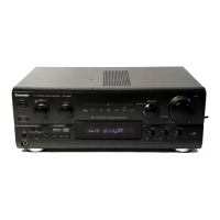
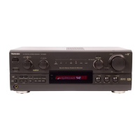
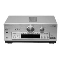
What to do if sound stops and 'OVERLOAD' appears on Technics Receiver?
- PplunaAug 5, 2025
If the sound stops and “OVERLOAD” appears on the display of your Technics Receiver, switch off the unit, determine and correct the cause, then switch the unit on. This issue may also arise from a shorting of the positive and negative speaker wires, using speakers with an impedance lower than rated for this unit (use speakers with the right impedance rating), straining of the speakers through excessive volume or power, or using the unit in a hot environment.