EasyManua.ls Logo

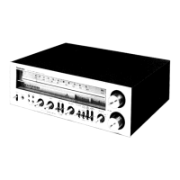
Technics QUARTZ SA-R177

Technics QUARTZ SA-R177
30 pages
To Next Page IconTo Next Page
Loading...
ORDER
NO.
AD8907222C3
Service
Manual
Receiver
CYUARTZ
Synthesizer
S
A-
R
4
77
AM/FM
Stereo
Receiver
Color
(K)...
Black
Type
Area
Country
(gn)
SPECIFICATIONS.
nin
45
500)
AMPLIFIER
SECTION
Power
output
Headphones
output
level
and
impedance
430
mV/330
Q
DIN
1kHz
2
x
50W(8Q)
Load
impedance
40
Hz~
20
kHz
continuous
power
output
AorB
8O~160
both
channels
driven
2
x
40W(8Q)
A
and
B
8
Q~16
0
Total
harmonic
distortion
rated
power
at
40
Hz~
20
kHz
0.3
%
(8
Q)
@i
FM
TUNER
SECTION
half
power
at
1
kHz
0.07
%
(8
Q)
Frequency
range
87.50
~
108.00
MHz
intermodulation
distortion
Sensitivity
rated
power
at
60
Hz:
7
kHz=
4:1,
SMPTE,
8
Q
0.5%
SIN
30
dB
1.5
pv
(75
Q)
Power
bandwidth
SIN
26
dB
1.3
WV
(75
Q)
both
channels
driven,
—3
dB
10
Hz~40
kHz
(8
Q)
SIN
20
dB
1.2
pV
(75
Q)
Damping
factor
__
20
(8Q)
IHF
usable
sensitivity
1.5
pV
(IHF'58,
75
Q)
sr
pclae
and
impedance
so
ileres
IHF
46
dB
stereo
quieting
sensitivity
22
pV/75
Q
mv/4
CD,
VCR
1,
TAPE/VCR
2
200
mV/22
kQ
ste
eri
almontion
soe
PHONO
maximum
input
voltage
(1
kHz,
RMS)
150
mV
STEREO
03
9%
SIN
Sin
=
rated
power
(8Q)
MONO
60
dB
(75
dB,
!HF)
PHONO
70
dB
(IHF,
A:
80
dB)
STEREO
58
dB
(7!
dB,
IHF)
Seatac
2
SO/GE
(IRIE
20
Oe)
Frequency
response
20
Hz~15
kHz,
+1
dB
~—-2
dB
PHONO
RIAA
standard
curve
lee
tiled
selectivity
fe
oe
+0.8
dB
(30
Hz~
15
kHz)
;
4
CD,
VCR
1,
TAPEIVCR
2
10
Hz~70
kHz
(+3
dB)
Ermeceeaieeue
of
:
5
band
graphic
equalizer
80
Hz,
—10
dB~
+10
dB
Spurious
response
rejection
at
98
MHz
70
dB
ee
eae
eupresion
8
2,
Stereo
separation
4
kHz,
—10
dB~
+10
dB
4
kHz
40
dB
12.5
kHz,
-10
d(B~+10
dB
10
kHz
30
dB
Loudness
control
(volume
at—30
dB)
50
Hz,
+9
dB
Carrier
leak
Output
voltage
19
kH
—30
dB
(—3§
dB,
IHF
VCR
1,
TAPEIVCR
2
REC
OUT
200
mV
ante
ero
ia
dG.
iB
Channel
balance,
250
Hz~6,300
Hz
md
Channel
balance
(250
Hz~
6,300
Hz)
+1.5
dB
Channel
separation
55
dB
Limiting
point
1.2
uv
i
echnics
Matsushita
Electric
Industrial
Co.,
Ltd.
Central
P.O.
Box
288,
Osaka
530-91,
Japan
Question and Answer IconNeed help?

Do you have a question about the Technics QUARTZ SA-R177 and is the answer not in the manual?

Technics QUARTZ SA-R177 Specifications

General IconGeneral
Tuning rangeFM, MW
Damping factor30
Input sensitivity2.5 mV (MM), 150 mV (line)
Frequency Response20Hz to 20kHz
Input Impedance47kΩ
Dimensions430 x 125 x 300mm
Output150mV (line)
Speaker load impedance8 ohms
Channel separation55 dB (1 kHz)

Summary

Receiver Specifications

Amplifier Section Specifications

Details power output, harmonic distortion, intermodulation distortion, power bandwidth, damping factor, input sensitivity, and frequency response.

FM Tuner Section Specifications

Details FM frequency range, sensitivity, signal-to-noise ratio, and total harmonic distortion for mono and stereo.

Unit Operation and Connection

Equipment Connection Guide

Illustrates and describes connections for speakers, antenna, remote control, and input/output terminals.

General Unit Information

Provides details on power consumption, power supply, dimensions, and weight of the unit.

Initial Setup and Operation

Pre-Operation Guide

Instructions on voltage selector adjustment and important notes for safe initial setup.

Remote Control Operation

Overview of the remote control transmitter and its button functions for various operations.

Included Accessories

Lists all items included in the package with the receiver.

Front Panel Controls

Amplifier Controls

Disassembly Instructions

Protection Circuitry

Repair and Adjustment Procedures

Before Repair Procedures

Safety instructions and procedures to follow before initiating any repair work on the unit.

Measurements and Adjustments

Procedures for measuring and adjusting various circuit parameters for optimal performance.

FM Adjustment Procedures

IC Terminal Functions

System Diagrams

System Block Diagram

Visual representation of the internal signal flow and main functional blocks of the receiver.

FL Display Internal Connections

Diagrams showing the grid assignment, pin connections, and anode connection table for the FL display.

Circuit Schematics

Component Layouts

Wiring and Assembly Diagrams

Wiring Connection Diagram

Illustrates how internal components and external connections are wired together within the unit.

Exploded Views

Visual breakdown of the unit's components, showing their relative positions for assembly and disassembly.

Parts List

Component Details

Resistors and Capacitors

Detailed list of all resistors and capacitors used in the unit, with their values and part numbers.

Related product manuals