EasyManua.ls Logo

Technics QUARTZ SA-GX100

Technics QUARTZ SA-GX100
33 pages
To Next Page IconTo Next Page
Loading...
Service
Manual
Receiver
CQUARTZ
Synthesizer
AM/FM
Stereo
Receiver
SPECIFICATIONS
(DIN
45
500)
@
AMPLIFIER
SECTION
Power
output
DIN
1
kHz
2x
40W(4Q)
40
Hz~20
kHz
continuous
power
output
both
channels
driven
2
x
30
W
(8
Q)
Total
harmonic
distortion
rated
power
at
40
Hz~20
kHz
0.5
%
(8
Q)
half
power
at
1
kHz
0.03
%
(8
Q)
‘ntermodulation
distortion
rated
power
at
60
Hz:
7
kHz=4:1,
SMPTE,
8
©
0.5
%
Power
bandwidth
both
channels
driven,
—3
dB
10
Hz~40
kHz
(8
Q)
Damping
factor
40
(8
Q)
Input
sensitivity
and
impedance
PHONO
3
mV/47
kQ
CD,
VCR
1,
TAPE/VCR
2
:
200
mV/22
kQ
PHONO
maximum
input
voltage
(1
kHz,
RMS)
150
mV
SIN
rated
power
(8
©)
PHONO
70
dB
(IHF,
A:
80
dB)
CD,
VCR
1,
TAPE/VCR
2
80
dB
(IHF,
A:
90
dB)
._
Frequency
response
PHONO
RIAA
standard
curve
+0.8
dB
(30
Hz~15
kHz)
CD,
VCR
1,
TAPE/VCR
2
10
Hz~40
kHz
(+3
dB)
Bass
50
Hz,
+10
dB~—10
dB
Treble
20
kHz,
+10
dB~—10
dB
Technics
SA-GX100
Color
(K)...
Black
Type
Area
Loudness
control
(volume
at
—30
dB)
50
Hz,
+9 dB
Output
voltage
VCR
1
AUDIO
OUT,
TAPE/VCR
2
REC
OUT
200
mV
Channel
balance,
250
Hz~6,300
Hz
+1
dB
Channel
separation
§5
dB
Headphones
output
level
and
impedance
430
mMW/BO
Q
Load
impedance
AorB
40O™M6Q
A
and
B
8N™60
MM
FM
TUNER
SECTION
Frequency
range
87.50~
108.00
MHz
Sensitivity
SIN
30
dB
;
1.5
uv
(15
Q)
SIN
26
dB
;
1.3
yV
(15
Q)
S/N
20
dB
1.2
uV
(15
Q)
IHF
usable
sensitivity
1.5
pV
(IHF'58,
156
)
IHF
46
dB
stereo
quieting
sensitivity
22
wr
Q
Total
harmonic
distortion
MONO
C2
%
STEREO
(3
%
SIN
MONO
;
60
dB
(75
dB,
IHF)
STEREO
58
dB
(71
dB
FF)
Frequency
response
20
Hz~15
kHz,
+1
dB~~-2
dB
Matsushita
Electric
Industrial
Co.,
_
td.
Central
P.O.
Box
288,
Osaka
530-91,
Jipan
'
Country
(EG)
F.R.
Germany
&
Italy.
Se
ae
Local
yee
Question and Answer IconNeed help?

Do you have a question about the Technics QUARTZ SA-GX100 and is the answer not in the manual?

Technics QUARTZ SA-GX100 Specifications

General IconGeneral
Total harmonic distortion0.05%
Speaker load impedance8Ω to 16Ω
Tuning rangeFM: 87.5 - 108 MHz
Input sensitivity150mV (line)
Dimensions430 x 135 x 310 mm
Power output100W per channel (8 ohms, 20Hz - 20kHz)

Summary

AMPLIFIER SECTION

FM TUNER SECTION

CONNECTIONS TO EQUIPMENT

FRONT PANEL CONTROLS AND FUNCTIONS

Amplifier Section Controls

Explains speaker selectors, muting/loudness indicators, tape indicator, volume, and tone controls.

TUNER SECTION CONTROLS

Tuning, Memory, and Mode Selection

Details tuning, memory operations, band selection, and FM mode.

REMOTE-CONTROL OPERATION

Tape Deck and Amplifier Controls

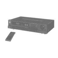
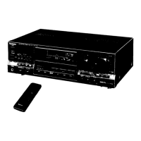
Describes remote control functions for tape decks and amplifier operations.

Tuner Controls

Details remote control operation for tuner functions like power and tuning.

PROTECTION CIRCUITRY

Circuit Function and Troubleshooting

Explains the protection circuit's purpose and how to troubleshoot activation.

BEFORE REPAIR AND ADJUSTMENTS

Pre-Repair Procedures

Outlines essential steps before starting repairs, including safety precautions.

DISASSEMBLY INSTRUCTIONS

DISASSEMBLY INSTRUCTIONS (Continued)

MEASUREMENTS AND ADJUSTMENTS

Adjustment Points and FM Mono Distortion

Identifies adjustment points and details FM mono distortion adjustment.

FM ADJUSTMENTS (Continued)

FM MPX VCO and Stereo Distortion Adjustment

Procedures for adjusting FM MPX VCO and FM stereo distortion.

TERMINAL FUNCTION OF IC

IC901 Microcomputer Pin Functions

Details pin functions for the microcomputer IC901.

BLOCK DIAGRAM

System Overview

A high-level block diagram illustrating the main functional blocks of the receiver.

SCHEMATIC DIAGRAM

Tuner Circuit Schematic

Detailed schematic for the FM and AM tuner sections.

Main Circuit Schematic

Schematic diagram for the main audio processing and control circuits.

SCHEMATIC DIAGRAM (Continued)

PRINTED CIRCUIT BOARDS

WIRING CONNECTION DIAGRAM

Power, AC, and Main PCB Wiring

Diagram showing wiring for power, AC input, main PCB, and tuner PCB.

EXPLODED VIEW

REPLACEMENT PARTS LIST

REPLACEMENT PARTS LIST (Continued)

Integrated Circuits (ICs)

Lists part numbers for all integrated circuits.

RESISTORS & CAPACITORS

Resistor List

Comprehensive list of resistors with part numbers and values.

Capacitor List

Comprehensive list of capacitors with part numbers and values.

RESISTORS & CAPACITORS (Continued)

Capacitor List (Continued)

Continues the list of capacitors with part numbers and values.

Related product manuals