EasyManuals Logo

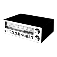
Technics QUARTZ SA-R177 User Manual

Technics QUARTZ SA-R177
30 pages
To Next Page IconTo Next Page
To Previous Page IconTo Previous Page
Page #15 background imageLoading...
Page #15 background image
@
SCHEMATIC
DIAGRAM
(Parts
list
on
pages
35
~
40)
(This
schematic
diagram
may
be
modified
at
any
time
with
the
development
of
new
technology.)
Note
1:
e
$601-1,
S601-2
:
Speaker
selectors.
$601-1:
A
S601-2:
B
S701
:
Power
“on/off”
switch.
@$702
:
Voltage
selector
switch.
(For
(G)
area.)
$901
~
$910
:
Preset-tuning
(1-0)
switches.
$901
:
CH1,
S902
:
CH2,
S903
:
CH3,
$904
:
CH4,
S905
:
CH5,
S906
:
CHG,
$907
:
CH7,
S908
:
CH8,
S909
:
CH9,
$910
:
CHO
es911
:
Music-scan/group-search
switch.
@$912
:
FM
mode
selector.
@
$913,
$914
:
Band
selectors.
"
$913:
FM,
S914:AM
@
$915,
$916
:
Tuning
switches.
$915:
W(DOWN),
S916:
A
(UP)
S917
:
Memory
switch.
S918
:
Loudness
switch.
eS919
~
$926
:
Group
registration
switches.
$919
:
start,
S920:
rock,
$921
:
jazz
$922
:
classic,
S923
:
easy,
S924
:
news
$925
:
other,
S926:
end
e@$927~S929,
_
:
Input
selector
switches.
$931
$927
:
phono,
$928
:
tuner,
S929
:
oo,|
ee
:VCR1
©
S930
:
Tape-monitor/VCR
2
switch.
®
Signal
line
coon
:
FM
OSC
<=>:
FM
signal
==B8)
-
AM
OSC
em
AM
signal
cz
:
Phono
signal
:
AF
signal
(Lch)
—(__}-
:
Positive
voltage
lines
--{__}--
:
Negative
voltage
lines
©
Important
safety
notice:
Components
identified
by
A.”
mark
have
special
characteristics
important
for
safety.
When
replacing
any
of
these
components,
use
only
manufacturer's
specified
parts.
Indicated
boltage
values
are
standard
values
for
the
unit
measured
by
the
DC
electronic
circuit
tester
(high-impedance)
with
the
chassis
taken
as
standard.
Therefore,
there
may
exist
some
errors
in
the
voltage
values,
depending
on
internal
impedance
of
the
DC
circuit
tester.
@
All
voltage
values
shown
in
circuitry
are
DC
voltage
in
FM
signal
(Stereo
signal)
reception
mode.
*
Figures
in
( )
Stand
for
DC-voltage
in
AM
signal
reception
mode.
*
Caution!
IC
and
LSI
are
sensitive
to
static
electricity.
Secondary
trouble
can
be
prevented
by
taking
care
during
repair.
*
Cover
the
parts
boxes
made
of
plastics
with
alminum
foil.
*
Ground
the
soldering
iron.
*
Put
a
conductive
mat
on
the
work
table.
*
Do
not
touch
the
legs
of
IC
or
LSI
with
the
fingers
directly.
Note2:
¢
Use
of
ceramic
filters
in
pairs
The
ceramic
filters
(CF
201,
CF202)
for
FM-IF
circuit
are
available
in
three
ranks.
For
this
circuit,
be
sure
to
use
the
ceramics
of
the
same
rank
in
a
pair.
At
repairing
and
replacement,
pay
close
attention
to
the
diodes
(D914,
D915)
for
use
as
different
diodes
must
be
used
depending
on
each
rank
of
the
ceramic
filters.
Color
marking
(Blue,
Red
or
Note:
©
mark:
Diode
is
used.
x
mark:
Diode
is
not
used.
a47
SA-R177
SA-R177
1
2 3
4
e
Remote-control
transmitter
(EUR64747)
B48
Chottering
simuhaneous|
push
inhibit
=lo
Lg
thee
S
x.
©
fz
2)
Key
input
contro!
circuit
Pulse
generation
circu
Pa
ei
eid
bie
He
be
ELL
|
ao
(Z)
we,
Ea
1
»
x
cA
ceAes
(2)
)
Timing
generation
circuit
(o)
O-®
aa
cl
M50467-O18FP
(4)
CONTROLLER
¢
Remote
control
data
code
Head
Custom
Inversion
Inversion
Data
code
Custom
code
Data
code
pulse
code
a,
*Data
“0”
«Data
"1"
UL
El
a
08
01100
|
ovotoo
|
aw
[Turere
|
ovoov
|
ovorns
|
foeckecmute
|
ore0r
|
ooornn
|
av
[umes
|
ovo01__|
010000
«[oecKniay«
|
o1oon
|
ooroor
[ae
[coe
|
_o11o0
|
_ovsou0
|
Pveunew
|
_or0o1
|
[ex
[coe
|
01100
|
or0001
Pruners
|
or001
|
Lo100
|
[eps
|
oto
[ae
—[oecx
pause]
—oraor
[0110
|
Trogariconinue
|
01100
[stare
|
oreo]
oro
11
[oop
|
ott00
|_
30
[tuner2
|
otoo1
|
oro001
foecxnays
[01001
[ao
[ooo
|
oreo
—or1001
|
Fvaunedom
|
—owor—tooror
|
1
Jone}
~on1oo
|
oro010
|
[DECK
stop
|
oro01__|__
000000
47
Tuner3
010010
feos
|
ort00
|
oro0nr
ee
:
[ocx
ve
[oreo
|
cootoo
[inere
[ooo]
—oroorr
°
8
forint
|
[copa
|
1100]
fossa
|
oor
|
21
[wing
|
voor
|
Pruner?
|
01001]
for
——*d
onto
_|
27
_[odsep
‘|
__on00
3/8
8
o|o
=
ae
8
:
ieee
3
8
3v
ai
Y
Teed
2SC3265Y
@)
LED
DRIVE
Error
Check
~
\35
ms
tear
TERY
18
FM
ANT.
(75)
GND
EY
AM
ANT
@
AM
LOOP
ANT.
EY
tuner(Fm/am)
circuit
Gno
Y
Loch
cd
©
r—
REC
ouT
©
VCR
|
LpLayBack
©
r-
REC
ouT
G
TAPE/VCR2
tpLavsack
©
Rech
co
©
r
REC
OUT
©
VCR
|
Uptayeack
©
r-
REC
out
©
TAPE/VCR2
UpLaysack
©
TNIOI(FM
FRONT
END
PACK)
RALOOO6M
2SK544
FM
RF
AMP
2SCI675LIL2
FM
OSC/BUFFER
AM
ANT
coil
AM
OSC
coil
c417
100P
ann
SS
eee
eee
C225
R233
18P
680K
Q2i0
2SCI740SQSTA
AM
OSC
BUFFER
t
875MH2-~IO8MHz
Vv
(aM)
U
~
Bx:
Q101,102
vk
BS
2SC2785FETA
ge
FM/AM
LooP
FILTER
VU,
5
30kH2
=~
1600kH?
C463
R457
457
C459
6.3V33
270
022
0.0068
C461
Se?
253.3
R461
R463
180K
i
*
C458
C460
0022
00068
R421
3.3K
|
WN
1c401
Essent
TC9I63N
INPUT
SELECTOR
R417
100K
WW
R418
100K
INPUT
SELECTOR
CIRCUIT

Questions and Answers:

Question and Answer IconNeed help?

Do you have a question about the Technics QUARTZ SA-R177 and is the answer not in the manual?

Technics QUARTZ SA-R177 Specifications

General IconGeneral
BrandTechnics
ModelQUARTZ SA-R177
CategoryStereo Receiver
LanguageEnglish

Related product manuals