EasyManua.ls Logo

Technics SA-GX230

Technics SA-GX230
20 pages
To Next Page IconTo Next Page
Loading...
()
AV
Control
Stereo
Receiver
Service
Manual
ORDER
NO.
AD9206177C2
Receiver
SA-GX230
Colour
Area
SPECIFICATIONS
(DIN
45
500)
lI
AMPLIFIER
SECTION
Power
output
DIN
1
kHz
(T.H.D.
1%)
2x80
W
(4 Q)
40
Hz~20
kHz
continuous
power
output
both
channels
driven
2x50
М
(80)
Total
harmonic
distortion.
rated
power
at
40
Hz~20
kHz
-
:
0.5%
(8
О)
half
power
at
1
kHz
Intermodulation
distortion
rated
power
at
60
Hz:
7
kHz—4:1,
SMPTE
Power
bandwidth
both
channels
driven,
—3
dB
0.5%
(8
О)
10
Н2--40
kHz
(8
О)
Damping
factor
40
(8
Q)
Input
sensitivity
and
Impedance
:
PHONO
3
mV/47
КО
CD,
VCR
1
200
mV/22
КО
.
VCR2,
TAPE
.
200
mV/22
kQ
PHONO
maximum
input
voltage
(1
kHz,
AMS):
150
mV
S/N
at
rated
power
(8
©)
.
70
dB
(ІНЕ,
А:
80
dB)
РНОМО
CD,
VCR
1
80
dB
(IHF,
A:90
dB)
VCR
2,
TAPE
80
dB
(IHF,
A:90
dB)
Frequency
response
|
РНОМО
RIAA
standard
curve
|
+0.8
dB
(30
Hz~15
kHz)
CD,
VCR
1
10
Hz~40
kHz
(+3
dB)
VCR
2,
TAPE
10
Hz~40
kHz
(+3
dB)
Tone
controls
|
Bass
.
50
Hz,
+10
dB—
—10
dB
Treble
20
kHz,
+10
dB—
10
dB
Loudness
control
(volume
at
—30
dB)
50
Hz,
+9
dB
Output
voltage
VCR
1
OUT
200
mV
TAPE
REC
(OUT)
200
mV
Channel
balance,
250
Hz~6.3
kHz
+1
dB
Channel
separation
-
.
55
dB
Headphones
output
level
and
impedance
430
mV/330
Q
Load
impedance
40-160
80—16
Q
А
ог
В
А
апа
В
Technics
0.03%
(8
Q)
.
Suffix
for
E
ж
(ЕС)
Germany
and
Italy.
(К)
(5)
ll
FM
TUNER
SECTION
Frequency
range
Sensitivity
SIN
30
dB
.1.5
uV
(75
Q)
SIN
26
dB
1.3шУ
(75
О)
SIN
20
ав
_
|
1.2uV
(75
О)
IHF
usable
sensitivity
1.5
uV
(IHF'58,
75
О)
ІНЕ
46
dB
stereo
quieting
sensitivity
.
22
uV/75
О
Total
harmonic
distortion
MONO
.
0.2%
STEREO
|
0.3%
S/N
m
;
cd
MONO
60
dB
(75
dB,
IHF)
STEREO
58
dB
(71
dB,
IHF)
Frequency
response
20
Hz~15
kHz,
+1
dB—
—2
dB
Alternate
channel
selectivity
i
87.50~108.00
MHz
-
+400
kHz
65
dB
-
Capture
ratio
1.0
dB
Image
rejection
at
98
MHz
40
dB
IF
rejection
at
98
MHz
70
dB
Spurious
response
rejection
at
98
MHz
70
dB
AM
suppression
50
dB
Stereo
separation
_1kHz
-—
40
dB
Carrier
leak
19
kHz
—55
dB
(—60
dB,
IHF)
38
kHz
—50
dB
(—55
ав,
ІНЕ)
Channel
balance
(250
Н2--6.3
06
+
1.5
ав
Limiting
point
1.2
uV
Bandwidth
IF
amplifier
180
kHz
FM
demodulator
1000
kHz
Antenna
terminals
75
О
(unbalanced)
Question and Answer IconNeed help?

Do you have a question about the Technics SA-GX230 and is the answer not in the manual?

Technics SA-GX230 Specifications

General IconGeneral
Input Sensitivity2.5mV (MM), 200mV (line)
Tuning rangeFM, MW
Speaker load impedance8Ω to 16Ω
Frequency Response20Hz to 20kHz
Signal-to-Noise Ratio90dB (line)
Dimensions430 x 130 x 310 mm (W x H x D)

Summary

Specifications Overview

Amplifier Section Specifications

Detailed specifications for power output, distortion, sensitivity, and tone controls of the amplifier section.

FM Tuner Section Specifications

Covers FM tuner frequency range, sensitivity, selectivity, image rejection, and distortion parameters.

AM Tuner Section Specifications

Lists AM tuner frequency range, sensitivity, selectivity, and image rejection for different regions.

General and Transmitter Specifications

Includes power consumption, dimensions, weight, and remote control transmitter details.

Unit Connections and Controls

Rear Panel Terminals and Functions

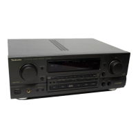
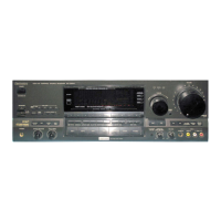
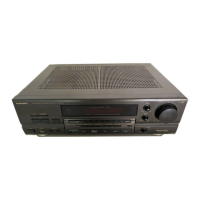
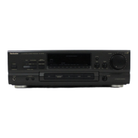
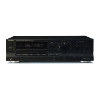
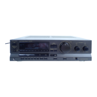
Explanation of all input/output connectors and controls found on the rear panel of the receiver.

Front Panel Controls and Functions

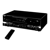
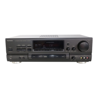
Guide to the buttons, indicators, and displays on the front panel for operation.

Remote Control Operation Guide

Instructions on how to use the remote control transmitter to operate various receiver functions.

Maintenance and Troubleshooting

Disassembly Instructions

Step-by-step procedures for safely dismantling the unit, including component removal.

Internal Component Removal Procedures

Detailed steps for removing specific internal PCBs and components like volume, tuner, and power supply.

Measurements and Adjustment Procedures

Guidelines for measuring electrical characteristics and performing adjustments, particularly for the FM section.

Block Diagram and Schematic Diagrams

Visual representation of the receiver's signal flow and detailed electronic circuit schematics.

Component and Parts Information

Wiring Connection Diagram

Illustrates the internal wiring connections between various printed circuit boards and components.

Component Terminal and Function Guide

Details the pin functions for ICs, transistors, and diodes, and internal connections.

Cabinet Parts Location and Replacement Parts

Visual guide to cabinet parts and a comprehensive list of replaceable components with part numbers.

Resistors and Capacitors Details

Specific listing of resistors and capacitors with their values, part numbers, and remarks.

Packaging Information

Information on packaging materials and procedures, including battery installation for the remote control.

Related product manuals