EasyManua.ls Logo

Technics SA-GX550 Service Manual

Technics SA-GX550
44 pages
To Next Page IconTo Next Page
Page #1 background imageLoading...
Page #1 background image
AV
Control
Stereo
Receiver
DiC
[eater
sunnauno|
PRO+LOGIC
SPECIFICATIONS
(DIN
45
500)
@
AMPLIFIER
SECTION
Power
output
(at
240
V)
DIN
1kHz
(T.H.D.
1%)
20Hz-—20kHz
continuous
power
output
both
channels
driven
Total
harmonic
distortion
rated
power
at
20Hz-—
20kHz
half
power
at
1kHz
Power
output
at
the
Dolby
Pro
Logic
operation
DIN
1kHz
(T.H.D.
1%)
2x
100W
(4Q)
2x
65
W
(8Q)
0.05%
(8Q)
0.03%
(8Q)
Front
2x
60W
(4Q)
Center
60W
(4Q)
Rear
20W
(4Q)
Intermodulation
distortion
rated
power
at
60Hz:
7kHz=4:
1,
SMPTE
Power
bandwidth
both
channels
driven,
—3dB
0.5%
(8Q)
10Hz—40kHz
(8Q)
Damping
factor
40
(8Q)
Input
sensitivity
and
impedance
PHONO
3mV/47kQ
CD,
VCR
1,
VCR
2,
TAPE/DCC
200
mV/22kQ
S/N
at
rated
power
(8Q)
PHONO
70dB
(IHF,
A:
80dB)
CD,
VCR
1,
VCR
2,
TAPE/DCC
75dB
(IHF,
A:
88dB)
Frequency
response
PHONO
RIAA
standard
curve
(830Hz—15kHz)
+0.8dB
CD,
VCR
1,
VCR
2,
TAPE/DCC
10Hz—40kHz,
+3dB
Tone
controls
BASS
50Hz,
+10
to
—10dB
TREBLE
20kHz,
+10
to
—10dB
Loudness
control
(volume
at
—30dB)
50Hz,
+9dB
Technics
ORDER
NO.
AD9306190C8
ervice
Manual
Receiver
SA-GX550
Colour
(K)...
Black
Type
Area
Suffix
for
Ares
Model
No.
|
©)
[Europe
|
eS
Asia,
Latin
America,
Middle
Near
East
and
Africa.
*
Manufactured
under
license
from
Dolby
Laboratories
Licensing
Corporation.
Additionnally
licensed
under
one
or
more
of
the
following
patents:
U.S.
numbers
3,632,886,
3,746,792
and
3,959,590;
Canadian
numbers
1,004,603
and
1,037,877.
“Dolby”
and
the
double-D
symbol
are
trademarks
of
Dolby
Laboratories
Licensing
Corporation.
Output
voltage
VCR
1
OUT,
TAPE/DCC
REC
(OUT)
200mV
Channel
balance
(250
Hz
6.3kHz)
+1dB
Channel
separation
55dB
Headphones
output
level
and
impedance
430mV/330Q
Load
impedance
AorB
4-160
A
and
B
8-160
FM
TUNER
SECTION
Frequency
range
87.50—
108.00
MHz
Sensitivity
S/N
30dB
1.5yuV/750
SIN
26dB
1.3uV/75Q
SIN
20dB
1.2uV/75Q
IHF
usable
sensitivity
(IHF
’58)
1.5WV/75Q
IHF
46dB
stereo
quieting
sensitivity
22uV/75Q
Total
harmonic
distortion
MONO
0.2%
STEREO
0.3%
SIN
MONO
60dB
(75dB,
IHF)
STEREO
58dB
(71dB,
IHF)
Frequency
response
20Hz—15kHz,
+1dB,
—2dB
Alternate
channel
selectivity
+400kHz
65dB
Capture
ratio
1.0dB
Image
rejection
at
98
MHz
40dB
IF
rejection
at
98
MHz
70dB
Spurious
response
rejection
at
98
MHz
70dB

Other manuals for Technics SA-GX550

Question and Answer IconNeed help?

Do you have a question about the Technics SA-GX550 and is the answer not in the manual?

Technics SA-GX550 Specifications

General IconGeneral
BrandTechnics
ModelSA-GX550
CategoryStereo Receiver
LanguageEnglish

Summary

PRODUCT SPECIFICATIONS

Amplifier Section Details

Detailed specifications for the audio amplification stage, including power output and distortion.

FM Tuner Section Details

Technical specifications related to the FM radio tuner, including frequency range and sensitivity.

TUNER AND GENERAL SPECIFICATIONS

AM Tuner, Video, and General Specs

Lists AM tuner ranges, sensitivities, video section specs, and general unit parameters like power and dimensions.

Transmitter Features and Operation

Information on control keys, dimensions, weight, power source, and basic operation of the remote.

AC MAINS LEAD SAFETY PRECAUTIONS

Fuse Replacement and Electrical Safety

Instructions for fuse replacement and essential electrical safety precautions for the mains lead.

FRONT PANEL CONTROLS OVERVIEW

Control Section Identification

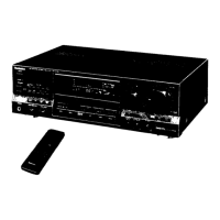
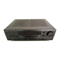
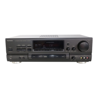
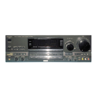
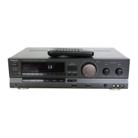
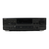
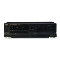
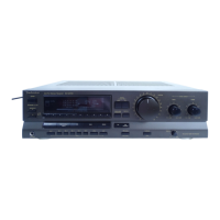
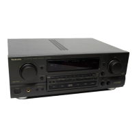
Identifies and describes the main control buttons and indicators on the front panel of the receiver.

DISPLAY SECTION AND ACCESSORIES LIST

Indicators, Displays, and Included Items

Explains receiver indicators, displays, and lists all provided accessories with their part numbers.

EQUIPMENT CONNECTION GUIDELINES

Audio/Video Connectivity and Voltage Setting

Guides on connecting audio sources, video equipment, and setting the unit's power voltage.

VIDEO EQUIPMENT CONNECTION DETAILS

Connecting Video Devices and Cables

Specific instructions for connecting VCRs and other video components using various cable types.

SPEAKER CONNECTION MANAGEMENT

Speaker Placement and Front Wiring

Guidance on speaker placement and connecting front speakers, including impedance considerations.

SPEAKER AND REMOTE CONTROL USAGE

Rear/Center Speaker Wiring & Battery Handling

Instructions for rear/center speaker connections and remote control battery installation/replacement.

REMOTE CONTROL OPERATION AND TROUBLESHOOTING

Usage, Range, and Failure Resolution

Guidelines on effective remote control operation, its range, and troubleshooting steps for failure.

RECEIVER OPERATING PROCEDURES

Basic Operations and Functions Guide

Instructions for fundamental receiver operations, including power, source selection, and volume adjustment.

RECEIVER BASIC FUNCTIONS AND TUNING

Tuning, Input Selection, and Operations

Detailed steps for tuning radio stations, selecting inputs, and performing basic receiver functions.

DISASSEMBLY INSTRUCTIONS FOR SERVICING

Cabinet, Panel, and PCB Removal Steps

Procedures for removing the cabinet, front panel, and internal printed circuit boards (PCBs).

COMPONENT P.C.B. REMOVAL PROCEDURES

Power Switch, Tuner, Transformer PCB Removal

Instructions for removing various PCBs including power switch, tuner, I/O terminal, and power transformer.

INTERNAL COMPONENT REMOVAL GUIDELINES

Power Supply, Main PCB, and Fan Motor Removal

Steps for removing power supply PCB, main PCB, and the cooling fan motor from the unit.

POWER IC AND P.C.B. MAINTENANCE GUIDE

Power IC/Transistor Removal and PCB Inspection

Procedures for removing power IC/transistor, checking the main PCB, and reassembly tips.

POWER IC AND REGULATOR REPLACEMENT GUIDE

Replacement Steps and Tool Recommendations

Detailed guide for replacing power IC/regulator, including tool usage and heat dissipation advice.

FAN MOTOR TROUBLESHOOTING AND IC TERMINALS

Fan Motor Diagnostics and IC Pinouts

Guide for diagnosing fan motor issues and a detailed pinout for the microcomputer IC901.

SYSTEM BLOCK DIAGRAM OVERVIEW

Overall System Architecture and Signal Flow

A visual representation of the receiver's internal circuitry and signal flow.

PROTECTION CIRCUITRY AND REPAIR PREPARATION

Protection Circuit Issues and Repair Safety Precautions

Information on the protection circuit, troubleshooting, and crucial safety steps before repair.

Component Terminal Identification Guide

A reference list of common ICs, transistors, and diodes used in the unit with their respective part numbers.

SCHEMATIC DIAGRAM INTERPRETATION

Diagram Notes, Cautions, and Handling ICs/LSIs

Explains schematic conventions, voltage notations, and essential precautions for handling ICs and LSIs.

PRINTED CIRCUIT BOARD LAYOUTS AND IDENTIFICATION

PCB Identification and Component Placement Diagrams

Visual diagrams showing the layout and component placement for various PCBs within the receiver.

REPLACEMENT PARTS CATALOG AND SAFETY NOTICES

Parts List and Important Safety Information

A comprehensive catalog of all replaceable parts, including important safety notices and part usage notes.

PACKAGING AND ACCESSORY DETAILS

Packaging Diagrams and Accessory Identification

Illustrates packaging contents, accessory identification, and regional variations for packaging components.

Related product manuals