EasyManua.ls Logo

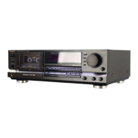
Technics RS-B965

Technics RS-B965
54 pages
To Next Page IconTo Next Page
To Previous Page IconTo Previous Page
Loading...
RS-B965
a
__1—__22____i—
|
g
TROUBLESHOOTING
OF
DIRECT
DRIVE
MOTOR
e
OUTLINE
OF
THE
DIRECT
DRIVE
MOTOR
SYSTEM
The
capstan
motor
is
actuated
by
the
DD
motor
digital!
servo
system.
The
FG
pulse
is
generated
after
the
detection
of
the
zero
crosspoint,
and
the
reference
signal
generated
from
the
quartz
oscillator
is
compared
with
this
FG
pulse.
From
this
comparison,
the
accelerated
and
reduced
speed
pulses
are
generated,
causing
the
driving
coil
to
function.
Ov
FG
SIGNAL
ro
ee
FG
PULSE
|
|
|
|
|
|
|
CLOCK
PULSE
SPEED
UP
PULSE
AMP
ORIVER
n
rt
SPEED
DOWN
PULSE
¢
TROUBLESHOOTING
OF
DIRECT
DRIVE
MOTOR
1.
No
power
supply
(+
12V)
2.
The
Hail
element
has
failed
(Current
does
not
flow).
3.
The
ceramic
(or
crystal)
does
not
oscillate.
Check
Points
1.
The
motor
does
not
rotate.
¢
Check
the
voitage
applied
to
the
connector.
¢
Check
the
DC
potential
on
10201
pins
@~@.
*
Check
the
waveform
of
I@201
pin
(2.
*
Check
the
conductance
of
the
coil.
if
normal,
the
resistances
between
IC201
pins
(@~d?,
@M~@B,
®~@®,
will
reach
200hms.'
¢
Check
the
waveform
of
IC-201
pins
Q~@D.
*
Check
the
waveform
of
IC
pin
©.
e
Check
if
the
FG
coil
is
broken.
2.
The
motor
does
not
rotate
|
1.
The
coil
is
broken
or
not
properly
soldered.
properly.
(When
pressed,
|
2.
Output
of
the
Hail
element
is
not
proper.
it
stops
at
certain
angles.
Sometimes
it
does
not
rotate
even
if
power
is
ON.)
3.
The
motor
is
out
of
1.
The
FG
coil
is
broken.
control.
4.
Abnormal
wow
1.
Same
as
those
described
for
problem
2.
Note:
Check
the
points
marked
with
an
asterisk
(*)
by
removing
the
DD
motor
control
P.C.B.
and
then
connecting
IC201
pin
@
to
GND
with
a
lead
wire.
(After
the
DD
motor
control
P.C.B.
is
removed,
current
will
start
flowing
through
the
coil,
heating
the
IC.)
38

Other manuals for Technics RS-B965

Related product manuals