EasyManua.ls Logo

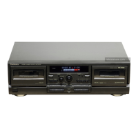
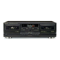
Technics RS-TR474

Technics RS-TR474
50 pages
To Next Page IconTo Next Page
To Previous Page IconTo Previous Page
Loading...
RS-TR474
|
Hi
TROUBLESHOOTING
GUIDE
*To
perform
troubleshooting,
set
the
unit
to
the
state
described
in
the
“Motor
Control
PCB
Checking
Method”
on
page
22.
The
unit
is
not
turned
on.
YES
Does
the
power
switch
turn
on
?
Is
the
voltage
output
at
Q608
emitter
approx.
5.6V
?
,
Is
the
voltage
across
R624
approx.
16V
?
NO
R624
replacement.
turned
on
and
off
?
turned
on
and
off
?
measured
?
FFC
cable
insertion
check
or
—..
replacement.
Does
the
voltage
at
Q603
base
change
from
OV
to
3.6V
when
measured
with
the
power
switch
Does
the
voltage
at
CN3B
pin
12
change
from
OV
to
5V
when
measured
with
the
power
switch
Does
the
voltage
at
CN3A
pin
12
change
from
OV
to
5V
when
Microprocessor
is
normal.
Does
the
voltage
at
Q603
collector
change
from
OV
to
15V
?
Q603
soldering
check
or
replacement.
Q610
and
—20V
system
check.
}—
Does
the
voltage
at
Q604
collector
change
from
—20V
to
15V
?
D613
soldering
check
or
replacement.
R622
disconnection,
or
Q605
check
or
replacement.
;
Does
the
voltage
at
D613
change
fromOVto8.2V?
.
Does
the
voltage
at
Q605
emitter
change
from
—0.4V
to
7V
Power
is
normal
|
RS-TR474
RS-TR474
Power
switch
turns
on
but
mechanism
does
not
operate
(common
to
both
mechanism).
Voltage
check:
Approx.
5V
at
CN1
pin
9
and
CN2
pin
14
Approx.
7.5V
at
CN1
pin
13
and
CN2
pin
12
Connection
a
Approx.
15V
at
CN1
pin
10
and
CN2
pin
13
OV
(ground)
at
CN1
pin
12
and
CN2
pin
10
NO
Do
open/close
operations
work
properly
?
YES
Check
switches
in
the
self-
diagnosis
mode.
Is
any
switch
failure
stored
in
YES
Replace
any
°
memory
?
new
one.
YES
NO
DECK
1:
$801,
S802
DECK
2:
S803,
S804
Unplug
the
power
cord
and
force
.
the
door
to
the
half-open
position
by
hand.
When
it
is
plugged
in
again,
YES
|
Both
power
a
check
the
door
closes
correctly
system
are
ni
with
both
door
switches
(S801
and
$802)
still
in
the
off
positions.
NO
DECK
1:
S801,
$802,
CN1
@
DECK
2:
$803, S804,
CN2
®
Does
the
voltage
at
CN1
pin
3
change
when
the
door
switch
NO
Switch
failure
(S801
and
$802)
is
forced
into
the
on
position
?
YES
DECK
1:
@
DECK
2:@
Does
the
voltage
at
the
oa
microprocessor
terminal
also
change
?
YES
:
Check
conne:
motor
PCB
ar
To
the
microprocessor
check
:
section.

Other manuals for Technics RS-TR474

Related product manuals