Do you have a question about the Technics RS-TR272 and is the answer not in the manual?
Describes deck system, track system, recording system, bias frequency, erasing system, and heads.
Procedures for checking mechanism control, FL, and Dolby noise reduction PCBs.
Steps for writing data to a new EEPROM after replacement.
Step-by-step procedure for rewriting adjusted values.
Procedure for adjusting playback gain.
Procedure for overall gain and frequency characteristic adjustments.
Procedure for adjusting head azimuth.
Procedure for adjusting tape speed.
General safety precautions for component handling and static electricity.
Visual layout of components on Deck 2 mechanism control PCB.
Component layout for Deck 1 mechanism control PCB.
Wiring diagram for the main PCB to other sections.
Diagram showing part locations for Deck 1 playback mechanism.
Diagram showing part locations for Deck 2 mechanism.
List of mechanical parts for Deck 1.
List of mechanical parts for Deck 2.
List of replacement resistors.
More resistors.
List of replacement capacitors.
| Track System | 4-track, 2-channel stereo |
|---|---|
| Tape Speed | 4.8 cm/s |
| Signal to Noise Ratio (Normal Tape) | 58dB |
| Signal to Noise Ratio (Chrome Tape) | 60dB |
| Signal to Noise Ratio (Metal Tape) | 62dB |
| Signal to Noise Ratio (Dolby B) | 68dB |
| Dimensions (W x H x D) | 430 x 125 x 290mm |
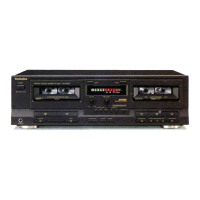
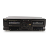
| Type | Double Cassette Deck |
| Frequency Response (Normal Tape) | 30 Hz - 14 kHz |
| Frequency Response (Chrome Tape) | 30 Hz - 16 kHz |
| Wow and Flutter | 0.08% WRMS |
| Power Supply | AC 120V |
| Heads | 2 x playback/record, 2 x erase |