EasyManua.ls Logo

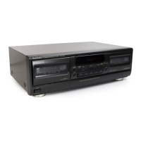
Technics RS-TR474

Technics RS-TR474
50 pages
To Next Page IconTo Next Page
To Previous Page IconTo Previous Page
Loading...
Microprocessor
check
section
Is
the
voltage
at
Microprocessor
NO
pin
57
approx.
5V
?
Is
the
voltage
at
Microprocessor
pin
60
approx.
5V
?
Is
the
voltage
at
Microprocessor
pin
240V?
Is
the
voltage
at
Microprocessor
,
pin
59
OV
?
Ne
YES
Is
the
clock
oscillating
?
(check
with
an
oscilloscope
and
1:10
probe.)
Connection
and
power
check.
NO
Are
there
pulses
at
microprocessor
pin
18
and
CN3
pin
12?
NO
Check
power,
D601
and
D602
circuits
and
their
connections.
audio
circuit
Does
failure
occur
in
audio
circuit
or
tape
mechanism
?
Te
she-audlo-cireult
tape
mechanism
To
the
tape
mechanism.
Tape
mechanism
DECK
2:
iC701
@
Does
the
voltage
input
to
AD
change
as
each
operating
switch
is
pressed
?
NO
DECK
1:
Voltage
increases
from
0V
in
approx.
0.4V
increments
when
Power,
Stop,
F.
Play,
R.
Play,
FF
and
REW
buttons
are
pressed
in
that
order.
DECK
2:
:
Voltage
increases
from
0.4V
in
approx.
0.4V
increments
when
Stop,
F.
Play,
and
R.
Play
buttons
are
pressed
in
that
order.
Caution:
The
counter
reset
is
connected
to
other
mechanism
systems.
Example:
To
check
mechanism
1,
be
sure
to
press
the
counter
reset
switch
on
mechanism
2.
Check
continuity
of
switches
whose
voitage
does
not
change
when
pressed.
In
case
of
failure,
replace
with
new
switches.
DECK
1:
1C701
@
or
W701
©
Q
-
Tape
mechanism
2
Tape
mechanism
1
Does
the
voltage
at
microprocessor
pin
64
change
when
S801
and
S802
of
the
mechanism
PCB
(or
the
leaf
switch
of
the
mechanism)
are
forced
into
the
on
positions
?
Does
the
voltage
at
microprocessor
pin
2
change
when
S803
and
$804
of
the
mechanism
PCB
(or
the
CrO,
Metal
switches
of
the
mechanism)
are
forced
into
t
on
positions
(A
D1
D2)
?
YES
Connection
check
for
Connector
switch
failure.
Soldering
checks
Do
pulses
develop
at
microprocessor
pins
25,
27-71
28
when
the
mode
switch
is
pressed
on
?
Do
pulses
develop
at
microprocessor
pins
26,
27
and
28
when
the
mode
switch
is
pressed
on
?
Microprocessor
failure.
YES
Does
the
voltage
at
microprocessor
pin
1
change
when
switch
of
the
mechanis
(MODE,
Revers
REC
INH
and
HALF
SW)
are
forced
into
the
positions.
Do
similar
pulses
develop
at
CN1
pins
4,
5
and
6
of
mechanism
1
when
the
mode
switch
is
pressed
on
?
Connection
checks
for
connectors,
FFC
cable,
soldering,
etc.
YES
Are
pulses
applied
to
termina
13,
15
and
16
of
IC801
when
t
mode
switch
is
pressed
on
?
YES
Are
pulses
applied
to
terminals
13,
15
and
16
of
{C801
when
the
mode
switch
is
pressed
on
?
mi
Pattern
and
soldering
checks.
-
|
Plunger
failure.
Does
the
plunger
instantly
pull
in
|
NO
|
Q803, Q804,
D801,
D806,
D802,
Play
button
is
pressed
?
D804
failure.
1C801
or
IC802
failure.
Does
the
plunger
remain
pulled
in
during
FF/REW
operations
?
NO
YES
|
Belt
has
come
off.
Reel
motor
failure.
1C801
or
IC802
failure.
i
30

Other manuals for Technics RS-TR474

Related product manuals