EasyManua.ls Logo

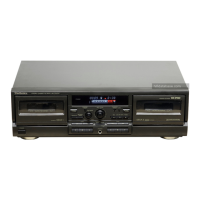
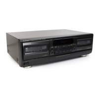
Technics RS-TR474

Technics RS-TR474
50 pages
To Next Page IconTo Next Page
To Previous Page IconTo Previous Page
Loading...
RS-TR474
|
Mi
TERMINAL
FUNCTION
OF
IC
°
10701
(M38123M4101F):
MICROCOMPUTER
*
To
check
the
contents
of
the
item
“3X”
in
the
IC
terminal
table,
set
the
unit
to
the
state
described
in
the
“Motor
Control
PCB
Checking
Method”
on
page
22.
Ho
, :
Rene
Connector
1
AD2D2
t
CN2A
©
pin
i
_
a
CN802
©
pin
3
|
METER-R
Rch
indication
level
input
|
Connector
;
P
CN3
@
pin
bh
bed
:
Connector
a
METER-L
1
Lch
indication
level
input
CN3
©
pin
, P
Normal:
“H”
(=4.8V)
|
sae
ae
:
‘a
ies
ee
i
=
weal
POWER
0
Power
control
output
ON:
Connector
Power
ON:
“H”
(=5V)
“H",
OFF:
“L”
CN3
@
pin
Power
OFF:
“L”
(=0V)
:
Normal:
“L”
(=0V)
MODEL
is
Model
selector
terminal
_
|
10701
©
pin
The
deck
malfunctions
when
set
to
“H”.
TPS
mode
No
program:
“H”
(=5V)
Programs:
“L”
(=0V)
No
tape
load:
Approx.
4.1V
Normal
tape
with
tab:
Approx.
2.3V
Deck
2
Mechanism
switch
(MODE,
RINH,
HALF)
input
No
tape
load:
Approx.
4.1V
Normal
tape
with
tab:
Approx.
OV
Chrome
tape
with
tab:
Approx.
1.1V
Metal
tape
with
tab:
Approx.
1.7V
Deck
2
Mechanism
switch
(FINH,
CrO.,
Metal,
OPEN/CLOSE)
input
Connector
CN2
©
pin
OV
with
no
signal
and
1V
with
OVU
(—20dB)
input
in
the
REC
or
PAUSE
mode.
The
voltage
varies
from
0
to
5V
for
different
input
levels.
TPS
signal
det.
input
ON:
Connector
CN3B
®
pin
“L”
(=0V)
when
sound
is
being
producedin
the
play
or
REC
mode
and “H”
(=2.5~5V)
when
no
sound
is
produced
in
the
stop
of
FF/REW
mode.
Connector
CN3
@
pin
Line
out
mute
signal
output
ON:
“L”,
OFF:
“H”
Connector
CN704
©
pin
CN704
©
pin
E2PROM
chip
select
signal
ON:
“H”,
OFF
“L”
(ex...For
t
REV
PLAY
i
IMSL
Atos
sere
is
changed)
5V
Waveform
appears
in
0
JILL
response
to
11
above.
(ex...For
+
REV
PLAY
5V
mode
is
changed)
0
ATL
MIL.
Waveform
appears
in
response
to
11
above.
14
PBADJ
Playback
adj.
output
ON:
Connector
Used
for
adjustment
at
factory
but
in
the
“H”,
OFF:
“L”
CN3
®
pin
finished
product.
Remains
at
“L”
(=0V).
Generated
signals
at
approx.
400Hz,
10kHz
and
15
osc
3kHz
(Square
wave
(H
and
L,
0
and
5V)
in
REC
16
STB
Strobe
(load)
output
for
the
Connector
DA
converter
(IC151)
CN3
©
pin
mode
during
adjustment
of
ATC).
Used
to
load
output
for the
DA
converter
(IC
151).
Remocon
signal
input
ON:
2701
bite
|
ats
OFF
cl
Connector
CN704
©
pin
CN704
@
pin
E2PROM
serial
clock
output
ON:
“L”,
OFF:
“H”
E2PROM
serial
data
input/output
Connector
-
CN704
©
pin
Connector
CN3
©
pin
Audio
signal
for
adjustment
output
H
and
L
pulse
waveform
appears
on
the
input
of
a
remote
control
signal.

Other manuals for Technics RS-TR474

Related product manuals