EasyManua.ls Logo

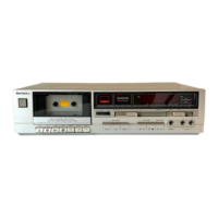
Technics RS-TR474

Technics RS-TR474
50 pages
To Next Page IconTo Next Page
To Previous Page IconTo Previous Page
Loading...
a
NI
fo7]
ao
S
pers
Ver
Deck
1
reel
pulse
det.
input
(take
up
side)
Deck
1
reel
pulse
det.
input
(supply
side)
Deck
2
reel
pulse
det.
input
(take
up
side)
Deck
2
ree!
pulse
det.
input
(supply
side)
Microcomputer
terminal
FL
meter
pull
down
voltage
input
terminal
GND
terminal
(A/D)
Reference
power
supply
(+5V)
(A/D)
Key
switch
input
Key
switch
input
Model
selector
terminal
Deck
1
Mechanism
switch
(FINH,
CrO.,
Metal,
OPEN/CLOSE)
input
TRANSISTOR
Q703
collector
|
TRANSISTOR
Q704
collector
TRANSISTOR
Q705
collector
TRANSISTOR
Q706
collector
Connector
CN3
@
pin
Connector
CN3
@
pin
Connector
CN3
@
pin
Connector
CN3
@
pin
CN1
©
pin
CN2
©
pin
10701
©
pin
1C701
€&
pin
16701
@
pin
Connector
CN1
©
pin
Chances
within
the
0
5V
range
each
time
the
take
up
reel
on
deck
1
is
through
approximately
30
degrees.
Supply
reel
on
deck
1
Fast
FF/REW
mode
is
disabled
unless
both
signals
53
and
54
are
active.
.
Take
up
ree!
on
deck
2
Supply
reel
on
deck
2
Fast
FF/REW
mode
is
disabled
unless
both
signals
55
and
56
are
active.
+5V,
Backup
Can
be
checked
at
pin
7
of
connector
CN801
or
at
pin
9
of
CN802.
DECK
1:
When
no
key
is
pressed:
5V
When
Stop
key
is
pressed:
0.4V
When
Power
key
is
pressed:
0V
When
any
other
key
is
pressed:
0
to
5V
DECK
2:
When
no
key
is
pressed:
5V
When
Stop
key
is
pressed:
0.4V
When
any
other
key
is
pressed:
0
to
5V
Change
the
voltage
at
this
pin
to
match
microprocessor
operation
to
the
individual
model.
TR474:
Approx.
1.2V
No
tape
loaded:
Approx.
4.1V
Normal
tape
with
tab:
Approx.
2.3V
Chrome
tape
with
tab:
Approx.
3.5V
Metal
tape
with
tab:
Approx.
3.5V

Other manuals for Technics RS-TR474

Related product manuals