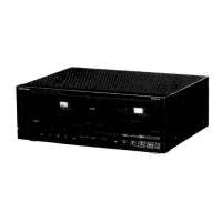
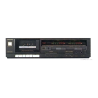
RS-X501
M@CONTENTS
Page
Page
ACCESSORIES.
..........sccccsscsssseessssevecsnesanscusevsensesnesnasensnneessanaoes
2
PRINTED
CIRCUIT
BOARDG.................:..::csccsssessessecsasee
26~30
CONNECTIONG.
.........:cssssseccssscsscesserseessesseeansenee
:
mee
4
WIRING
CONNECTION
DIAGRAM
.........-.ccc.ccccccssscssccesssssone
31
FRONT
PANEL
CONTROLS
AND
FUNCTIONS.
ae
3,
4
REPLACEMENT
PARTS
LIST..........
..
32~34
DISASSEMBLY
INSTRUCTIONG.............cccssscsssssessctensneesees
5~8
PACKING
soscccncecos2occtscecécaucte
cassie
seendeastansccsvscessaetcersccceetvontectoenss
34
MESUREMENT
AND
ADJUSTMENT
METHODEG.........
9~11
EXPLODED
VIEW
(Cabinet
parts)...
ws
35,
36
TERMINAL
FUNCTION
OF
IC’S..........cccscssscessssssscenessees
REPLACEMENT
PARTS
LIST.................
wee
Of,
38
BLOCK
DIAGRAM...........:scscncesreerssees
as
EXPLODED
VIEWS
(Mechanical
parts).
.
39~42
INTERNAL
CONNECTION
OF
FL...
REPLACEMENT
PARTS
LIST
...........:..0ccscessscsansessceeseeeennveres
43
SCHEMATIC
DIAGRAM
.......c:c::csseccscesenesssssnerssenecenenesees
RESISTORS
&
CAPACITORS.
.............:c0csssecsstessssensoees
44,
45
TERMINAL
GUIDE
OF
IC’S,
TRANSISTORS
AND
DIODEG............-cssccssscessereerseserees
25
li
ACCESSORIES
e
Stereo
connection
cables........
2
L-type
cable.................0..
1
e
AC
power
supply
cord...........
1
(SJP2249-3)
(SJP2257T)
SFDACO5E03:
(E,
EG)
SJA188:
(EB)
RJA0004:
(GC)
SJA173:
(GN)
i
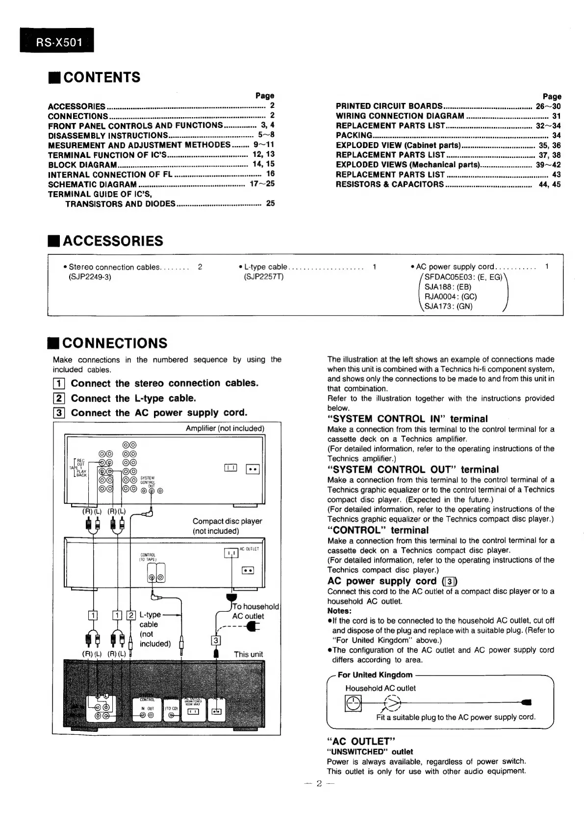
CONNECTIONS
Make
connections
in
the
numbered
sequence
by
using
the
included
cables.
[1]
Connect
the
stereo
connection
cables.
[2]
Connect
the
L-type
cable.
[3]
Connect
the
AC
power
supply
cord.
Amplifier
(not
included)
CONTROL
OUT
Compact
disc
player
(not
included)
CONTROL
(TO
TAPE)
To
household
AC
outlet
aoe
(R)
(L)
d
This
unit
‘CONTROL
UNSWITCHED
WOW
MAX
IN
OUT
{TO
CD)
ele
©
The
illustration
at
the
left
shows
an
example
of
connections
made
when
this
unit
is
combined
with
a
Technics
hi-fi
component
system,
and
shows
only
the
connections
to
be
made
to
and
from
this
unit
in
that
combination.
Refer
to
the
illustration
together
with
the
instructions
provided
below.
“SYSTEM
CONTROL
IN”
terminal
Make
a
connection
from
this
terminal
to
the
control
terminal
for
a
cassette
deck
on
a
Technics
amplifier.
(For
detailed
information,
refer
to
the
operating
instructions
of
the
Technics
amplifier.)
“SYSTEM
CONTROL
OUT”
terminal
Make
a
connection
from
this
terminal
to
the
contro!
terminal
of
a
Technics
graphic
equalizer
or
to
the
control
terminal
of
a
Technics
compact
disc
player.
(Expected
in
the
future.)
(For
detailed
information,
refer
to
the
operating
instructions
of
the
Technics
graphic
equalizer
or
the
Technics
compact
disc
player.)
“CONTROL”
terminal
Make
a
connection
from
this
terminal
to
the
control
terminal
for
a
cassette
deck
on
a
Technics
compact
disc
player.
(For
detailed
information,
refer
to
the
operating
instructions
of
the
Technics
compact
disc
player.)
AC
power
supply
cord
((3])
Connect
this
cord
to
the
AC
outlet
of
a
compact
disc
player
or
to
a
household
AC
outlet.
Notes:
elf
the
cord
is
to
be
connected
to
the
household
AC
outlet,
cut
off
and
dispose
of
the
plug
and
replace
with
a
suitable
plug.
(Refer
to
“For
United
Kingdom”
above.)
eThe
configuration
of
the
AC
outlet
and
AC
power
supply
cord
differs
according
to
area.
For
United
Kingdom
Household
AC
outlet
SS
_a
fa
Fit
a
suitable
plug
to
the
AC
power
supply
cord.
“AC
OUTLET”
“UNSWITCHED”
outlet
Power
is
always
available,
regardless
of
power
switch.
This
outlet
is
only
for
use
with
other
audio
equipment.
—2—-—
 Loading...