Do you have a question about the Technics RS-X501 and is the answer not in the manual?
Technical specifications for the cassette deck section and overall product.
Details on cables, power cords, system control terminals, and AC outlet.
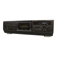
Explanation of front panel operational controls and status indicators.
Controls and indicators applicable to individual tape decks.
Procedures for removing cabinet, PCBs, and flat cables.
Procedures for removing PCBs and mechanism units.
Instructions for removing power switch, operation PCB, and eject mechanism parts.
Procedures for removing damper gears, holders, and the cassette lid.
Required measurement conditions, instruments, and identification of adjustment points.
Procedures for adjusting head azimuth, tape speed, playback gain, and frequency response.
Methods for calibrating erase current, overall frequency, and gain.
Detailed pin functions for the IC901 microcomputer.
Block diagrams of main, audio, Dolby NR, and FL meter circuits.
Block diagram of the IC551 microcomputer for FL meter operation.
Diagrams and table detailing FL display grid and anode connections.
Schematic diagrams for main, power switch, and mechanism circuits.
Schematic diagrams for Dolby NR and FL Meter circuits.
Schematic diagram for the operation circuit.
Visual layouts of main, mechanism, and power switch printed circuit boards.
Visual layouts of Dolby NR, FL Meter, and Operation circuit boards.
Wiring diagrams showing connections between panels, main PCB, and circuit boards.
List of integrated circuits, transistors, and diodes with part numbers.
List of resistors, capacitors, connectors, fuses, and switches.
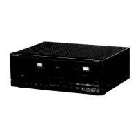
Exploded view of cabinet parts and external assemblies.
List of cabinet, chassis, buttons, knobs, and damper parts.
Detailed list of mechanical parts for tape deck 1.
Exploded views of Deck 1 mechanical parts from top and bottom.
Exploded views of Deck 2 mechanical parts from top and bottom.
Detailed list of mechanical parts for tape deck 2.
Lists of resistors and capacitors with their values and part numbers.
| Brand | Technics |
|---|---|
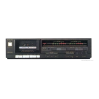
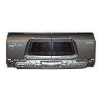
| Model | RS-X501 |
| Category | Cassette Player |
| Language | English |