Do you have a question about the Technics RS-M205 and is the answer not in the manual?
Details track system, tape speed, wow/flutter, frequency response, signal-to-noise ratio, and response times.
Covers input/output levels, bias frequency, motor, heads, power requirements, dimensions, and weight.
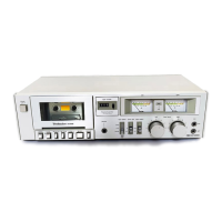
Identifies power, eject, play, stop, rewind, fast forward, pause, input/tape selectors, and Dolby NR switch.
Describes recording lamp, VU meters, and tape counter functions.
Illustrates removal of covers, front panel, and related components using figures.
Shows procedures for accessing internal units like the mechanism and meter via diagrams.
Details sequential steps for removing case cover, bottom cover, front panel, back chassis, mechanism, and meter units.
Identifies adjustment potentiometers (VRs) and test points (TPs) on internal components for calibration.
Pinpoints the location for tape speed adjustment and provides a note on tool usage.
Covers head position, azimuth adjustments, and tape speed accuracy calibration.
Details L-ch/R-ch output balance and phase adjustments using test tapes and equipment.
Explains measurement of tape speed fluctuation and playback frequency response calibration.
Details playback gain adjustment, erase current measurement, and overall frequency response calibration.
Guides on adjusting bias current for optimal recording frequency response using specific test tapes.
Illustrates graphical adjustments for frequency response based on recorded signal levels and charts.
Covers frequency response for CrO2/Metal tapes and overall gain adjustment procedures.
Details calibration of the level meter and adjustment of the Dolby NR circuit for proper operation.
Visual guides showing the placement of electrical components on the unit's chassis.
A comprehensive list of electrical components with part numbers for replacement purposes.
Detailed schematic diagrams for the Dolby NR and Record EQ amplifier circuits.
Schematics illustrating the headphone amplifier, meter drive circuits, and output stages.
Provides detailed schematics for the playback equalizer and microphone amplifier circuits.
Illustrates circuits involving integrated circuits (IC1, IC2, IC3) and bias generation components.
Explains component naming conventions (e.g., ERD, ECQ) and provides general circuit operational notes.
Lists replacement parts by reference number and includes equivalent circuit diagrams for key ICs.
Shows the wiring connections and layout for the main circuit board, including ICs and transistors.
Illustrates signal flow and connections for line inputs, microphone inputs, and head connections.
Visual representations of the arrangement of various mechanical parts within the cassette deck mechanism.
Provides notes on circuit polarity, voltage measurements, and part numbering for mechanical components.
Illustrates wiring for power selection, AC power switch, transformer connections, and meter circuits.
Explains part numbering conventions and voltage measurement notes for mechanical assemblies.
Shows exploded views and arrangement of mechanical parts like pulleys, gears, and arms.
A list of mechanical parts with their reference numbers, part numbers, and descriptions for servicing.
Illustrates the location and provides part numbers for various mechanical assemblies and sub-components.
Lists mechanical parts with reference numbers, part numbers, and descriptions for easy identification.
Diagrams showing the arrangement of mechanism parts and their corresponding part numbers.
Details mechanical specifications and lists replacement parts for the mechanism.
Illustrates the location of cabinet parts like covers, knobs, indicators, and nameplates.
Lists included accessories such as the instruction book and packing materials.
Provides a comparison table for updated part numbers and important safety notices.
Instructions on using the supplement with the original manual and Dolby trademark information.
Shows additions or changes to schematic and circuit board diagrams.
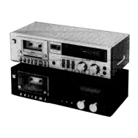
Illustrates differences in mechanical part locations between former and new types.
| Type | Cassette Deck |
|---|---|
| Track System | 4-track, 2-channel stereo |
| Tape Speed | 4.8 cm/s |
| Motor | DC servo motor |
| Tape Type | Normal, CrO2, Metal |
| Wow and Flutter | 0.07% (WRMS) |
| Dimensions | 430 x 118.5 x 230mm |