EasyManua.ls Logo

Technics RS-M14

Technics RS-M14
23 pages
To Next Page IconTo Next Page
Loading...
ORDER
NO.
ARD-8004036C
Service
Manual
Cassette
Deck
RS-M14
(
Silver
load
Black
Face
Metal
Tape
Compatible
Stereo
Cassette
Deck
with
Peak-Hold
FL
Meters,
Soft-Touch
Controls
and
Rewind
Auto-Play
Convenience
DO
[sacevavsrem)
This
is
the
Service
Manual
for
the
following
areas.
wees
For
all
European
areas
except
United
Kingdom.
s+
For
United
Kingdom.
cei
ass
For
Asia,
Latin
America,
Middle
East
and
Africa
areas.
Al
see
sires
For
Australia.
a
For
Asian
PX.
naib
ants
For
European
PX.
RS-M24
MECHANISM
SERIES
Specifications
Track
system:
4-track
2-channel
stereo
recording
and
playback
Outputs:
LINE;
output
level
420
mV,
output
impedance
Tape
speed:
4.8cm/s
1.5kQ
or
less,
load
impedance
22kQ
over
Wow
and
flutter:
0.05%
(WRMS),
+0.14%
(DIN)
oh
output
level
80mV,
load
imped-
;
2
ance
Prequeney
esponces
Metal
Tapes
oe
na
+
(DIN)
Rec/Pb
connection:
5P
DIN
type;
CrOo/Fe-Cr
tape:
20-18
000Hz
input
sensitivity
0.25
mV,
impedance
5.3kQ
:
pe;
3016
O00Hz
(DIN)
output
level
420
mV,
impedance
5.2kQ
Normal
tape:
20—17,000Hz
Bias
frequency:
80
kHz
30—15,000Hz
(DIN)
Motor:
Electrical
DC
governor
motor
Signal-to-noise
ratio:
Dolby
NR
in;
67
dB
(above
5kHz)
Heads
:
2-head
system;
1-MX
head
for
record/playback
Dolby
NR
out:
57
dB
(signal
level=max.
record-
i
disubiecera
tents
heatl
tov
amseults
ing
level,
Fe-Cr/CrOz
type
tape)
Fast
forward
and
Power
requirements:
AC;
110/125/220/240V,
50-60Hz
rewind
time:
Approx.
90
seconds
with
C-60
cassette
tape
Power
consumption:
15
W
(for
European
areas
and
Australia)
Inputs:
MIC;
sensitivity
0.25
mV,
input
impedance
25kQ
13
W
(for
Asia,
Latin
America,
Middle
East,
Africa
over
applicable
microphone
impedance
4002—
areas
and
PX.)
Dimensions:
43,0cm(W)
X
11.9cm(H)
x
24.6cm(D)
LINE;
sensitivity
60mV,
input
impedance
40kQ2
Weight:
4.3kg
Specifications
are
subject
to
change
without
notice.
*
‘Dolby’
and
the
double-D
symbol
are
trademarks
of
Dolby
Laboratories.
@
Panasonic
Tokyo
ec
|
2
1CS
Matsushita
Electric
Industrial
Co.,
Ltd.
Matsushita
Electric
Trading
Co.,
Ltd.
17-15,
6-chome,
Shinbashi,
Minato-ku,
Tokyo
105
Japan
P.O.
Box
288,
Central
Osaka
Japan
Question and Answer IconNeed help?

Do you have a question about the Technics RS-M14 and is the answer not in the manual?

Technics RS-M14 Specifications

General IconGeneral
Track System4-track, 2-channel stereo
Tape Speed4.8 cm/s
InputsLine In
OutputsLine Out, Headphone Out
MotorDC motor
Tape TypeCrO2, Metal
TypeStereo Cassette Deck

Summary

Specifications

Location of Controls and Components

Control Identification

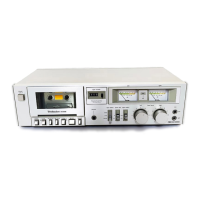
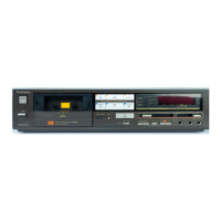
Identifies and describes all front panel controls and indicators.

Disassembly and Assembly Procedures

Disassembly Instructions

Step-by-step guide for taking the unit apart.

Disassembly Notes (Mechanism Unit)

Specific precautions and procedures for the mechanism.

Assembly Instructions

Steps for reassembling the unit after repair or maintenance.

Adjustment and Measurement Procedures

Adjustment Parts Location

Identifies adjustment points on the circuit board.

Head Position Adjustment

Procedure to adjust the tape head's vertical position.

Head Azimuth Adjustment

Procedure to adjust the tape head's horizontal alignment.

Tape Speed Adjustment

Procedure for setting the correct tape transport speed.

Tape Speed Fluctuation Measurement

Method to measure variations in tape speed.

Playback Frequency Response

How to measure the audio frequency range during playback.

Playback Gain Adjustment

Procedure to set the playback signal output level.

Bias Leakage Adjustment

Adjusting for minimal bias signal leakage.

Erase Current Adjustment

Setting the erase head current for proper tape erasure.

Bias Current Adjustment

Adjusting the bias current for optimal recording.

Overall Gain Adjustment

Setting the overall signal amplification level.

Overall Frequency Response

Measuring the frequency response across different tape types.

Fluorescent Meter Adjustment

Calibrating the level meters for accurate display.

Dolby NR Circuit Adjustment

Adjusting the Dolby noise reduction system.

Parts Identification and Location

Electrical Parts Location

Diagrams showing the placement of electronic components.

Cabinet Parts

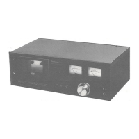
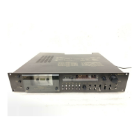
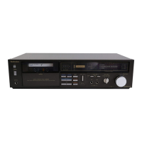
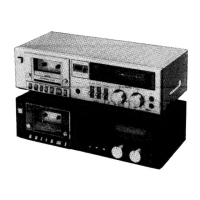
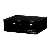
Identifies external and structural components of the unit.

Mechanical Parts Location

Diagrams showing the location of mechanical parts in the mechanism.

Related product manuals