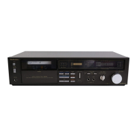
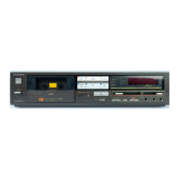
The Technics RS-M226 is a soft-touch cassette deck featuring Dolby B-C NR, designed for high-quality stereo recording and playback. This service manual provides comprehensive information for maintenance, adjustment, and repair, ensuring the device's optimal performance.
Function Description
The RS-M226 operates as a 4-track, 2-channel stereo recording and playback cassette deck. It is equipped to handle various tape types, including Metal, CrO2, and Normal, allowing users flexibility in their recording and listening preferences. The inclusion of Dolby B-C Noise Reduction (NR) significantly enhances audio quality by reducing tape hiss during both recording and playback, providing a cleaner and more dynamic sound experience. The deck supports both recording from external sources via its LINE IN and MIC inputs, and playback through LINE OUT jacks and a dedicated headphone jack.
Usage Features
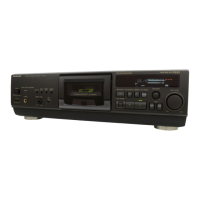
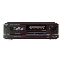
The front panel of the RS-M226 is designed for intuitive operation with soft-touch controls. Key features include:
- Power Switch: A push-on switch for turning the unit on and off.
- Eject Button: For opening the cassette holder to insert or remove tapes.
- Cassette Holder: Securely holds the cassette tape during operation.
- Tape Counter: A digital display that tracks tape position, aiding in locating specific sections.
- Counter Reset Button: Resets the tape counter to zero.
- Recording Indicator (rec): Illuminates to indicate that the unit is in record mode.
- Input Select Button: Allows selection between LINE and MIC inputs for recording.
- FL (fluorescent level) Meter: Provides a visual representation of input and output audio levels, helping users monitor and adjust recording levels to prevent distortion.
- Input Level Controls (L/R): Separate controls for adjusting the input level for left and right channels, enabling precise recording level adjustments.
- Tape Selector: A switch to select the appropriate tape type (Normal, CrO2, Metal), ensuring optimal recording and playback characteristics for each tape.
- Dolby Noise Reduction Select Switch: Allows users to choose between Dolby B NR, Dolby C NR, or no noise reduction, depending on the recording and playback requirements.
- Microphone Jacks (L/R): Dedicated inputs for connecting microphones for stereo recording.
- Fast Forward/Cue Button: Advances the tape quickly. When held during playback, it allows for "cue" functionality, enabling audible fast forwarding to locate specific passages.
- Rewind/Review Button: Rewinds the tape quickly. When held during playback, it provides "review" functionality, enabling audible fast rewinding.
- Play Button: Initiates tape playback.
- Stop Button: Stops all tape operations.
- Record Button: Engages record mode. This typically requires pressing the play button simultaneously to begin recording.
- Pause Button: Temporarily stops recording or playback, allowing for quick resumption without disengaging the main operation mode.
- AC Power Voltage Select Switch: Allows the user to select the appropriate AC power voltage (220V or 240V) for different regions.
- Line Output Jacks (L/R): For connecting the deck to an amplifier or receiver for audio output.
- Line Input Jacks (L/R): For connecting external audio sources (e.g., CD player, tuner) for recording.
- Headphones Jack: For private listening with headphones.
Maintenance Features
The service manual outlines detailed procedures for maintaining and adjusting the RS-M226 to ensure its longevity and performance. These include:
- Disassembly Instructions: Step-by-step guides for disassembling various components, such as the case cover, bottom cover, power supply circuit board, front panel, FL meter unit, main circuit board, mechanism unit, and cassette holder. This is crucial for accessing internal components for repair or replacement.
- Measurement and Adjustment Methods:
- Head Position Adjustment: A procedure to adjust the tape touch of the head in cue or review mode, ensuring proper tape-to-head contact. This involves measuring the space between the pressure roller and the capstan and adjusting a screw if necessary.
- Head Azimuth Adjustment (L-ch/R-ch Output Balance and Phase Adjustment): Critical for optimal stereo separation and frequency response. This involves playing an 8kHz test tape and adjusting a screw to achieve maximum and balanced output levels for both channels, as well as correct phase alignment.
- Tape Speed Accuracy and Fluctuation: Procedures to measure and adjust the tape speed using a test tape and a digital electronic counter. This ensures that recordings and playback occur at the correct speed, preventing pitch variations. Adjustment is made via a dedicated VR (variable resistor).
- Playback Frequency Response: Measurement of the unit's ability to reproduce a full range of frequencies during playback. This involves playing a frequency response test tape and comparing output levels across various frequencies to a specified chart.
- Playback Gain: Adjustment of the output level during playback to a standard value, ensuring consistent volume levels.
- Erase Current: Measurement and adjustment of the current supplied to the erase head, which is vital for effectively erasing previous recordings before new ones are made. This ensures clean recordings without residual audio.
- Overall Frequency Response (Recording Bias Current Adjustment): A comprehensive adjustment that involves recording and playing back signals across various frequencies for different tape types (Normal, CrO2, Metal). Bias current is adjusted via VRs to achieve the optimal frequency response for each tape type, ensuring accurate sound reproduction.
- Overall Gain: Adjustment of the unit's overall gain during recording and playback to standard levels, ensuring consistent signal strength.
- Fluorescent Meter Adjustment: Calibration of the FL meter to accurately display audio levels, ensuring proper monitoring during recording.
- Dolby NR Circuit Frequency Response Check: Detailed checks of both Dolby B and Dolby C encoder characteristics to ensure the noise reduction circuits are functioning correctly and providing accurate frequency compensation.
- Electrical Parts Location: Diagrams and lists identifying the location and part numbers of various electrical components, including heads, fuses, connectors, and circuit boards, facilitating easy identification and replacement.
- Mechanical Parts Location: Detailed diagrams and lists for all mechanical components, such as levers, springs, gears, and motors, which are essential for understanding the mechanism's operation and for replacing worn or damaged parts.
- Cabinet Parts Location: Lists and diagrams for external cabinet components, including knobs, buttons, and panels, for cosmetic repairs or replacements.
- Replacement Parts List: Provides part numbers and descriptions for all replaceable components, including safety-critical parts marked with an "A" that require specific manufacturer-approved replacements.
- Circuit Boards and Wiring Connection Diagram: Visual guides for the layout of circuit boards and the connections between them, aiding in troubleshooting and repair.
- Block Diagram and Schematic Diagram: Provide a high-level overview and detailed circuit diagrams, respectively, for understanding the electronic functionality of the deck.
- Equivalent Circuit: Shows the internal structure of integrated circuits (ICs) used in the device.
- Precautions for Mechanism Unit Assembly: Specific instructions to follow during the reassembly of the mechanism unit, such as setting levers and buttons to their correct positions, to ensure proper functionality.
This comprehensive manual ensures that technicians can effectively service the Technics RS-M226, maintaining its high-fidelity audio performance and operational reliability.