EasyManua.ls Logo

Technics SA-5460

Technics SA-5460
16 pages
To Next Page IconTo Next Page
Loading...
ORDER
NO.
SD7607-1101
ervice
Manual
FM/AM
STEREO
RECEIVER
SA-5460
(X),
(XG),
(XGH),
(XSD),
(XSW),
(XE)
TECHNICAL
SPECIFICATIONS
(IHF)
Specifications
are
subject
to
change
without
notice
for
further
improvement.
AMPLIFIER
SECTION
1kHz
continuous
power:
78W
+
78W
(41)
68W
+
68W
(82)
72W
+
72W
(40)
65W
+
65W
(82)
both
channles
driven
at
8
10Hz
~
40kHz,
—3dB
0.1%
at
rated
power
(20Hz
~
20kHz)
0.05%
at
half
power
(1kHz)
intermodulation
distortion:
0.5%
Damping
factor.
55
(80),
27.5
(4)
Input
sensitivity
and
impedance:
PHONO
2.5mV/47k1.
AUX,
TAPE
2
PLAYBACK
150mV/35kN.
TAPE
1
PLAYBACK,
REC/
PLAY
input
180mV/40k0.
both
channels
driven
20Hz
~
20kHz
continuous
power:
both
channels
driven
Power
bandwidth:
Total
harmonic
distortion:
PHONO
maximum
input
voltage:
(1kHz,
RMS)
150mV
S/N
(IHF,
A):
PHONO
78
dB
AUX
95dB
Frequency
response:
PHONO
RIAA
Standard
curve
40.2dB
AUX
20Hz
~
20kHz,
+0.5dB
Tone
controls:
BASS
50Hz,
+13dB
~—13dB
TREBLE
10kHz
+12dB
~—12dB
Loudness
control
(volume
at
—30dB):
50Hz,
+9dB
Output
voltage:
TAPE
1
REC
OUT
180mV
TAPE
2
REC
OUT
150mV
TAPE
1
REC/PLAY
output
30mV
7kHz
—6dB/oct.
100Hz,
—6dB/oct.
High
fillter:
Low
filter:
VERSTARKERTEIL
RMS-Dauertonleistung
bei
1kHz:
beide
Kanale
zusammen
ausgesteuert
2
x
78W
(429)
2
x
68W
(80)
RMS-Dauertonleistung
bei
20Hz
~
20kHz:
beide
Kanale
zusammen
ausgesteuert
2
x
72W
(40)
2
x
65W
(8)
Leistungsbandbreite
(beide
Kanale
zusammen
10Hz
~
40kHz,
—3dB
ausgesteuerbei
4()):
Harmonische
Verzerrungen:
Nennleistung
bei
40Hz
~
16,000Hz,
4M
0.1%
Intermodulationsverzerrung:
Nennleistung
bei
250Hz:
8000Hz
=
4:1
41)
0.5%
Dampfungsfaktor:
55
(8),27.5
(49)
Eingangsempfindlichkeit
&
Impedanz:
PHONO
2.5mV/47kN
AUX,
TAPE
2
PLAYBACK
150mV/35kN.
TAPE
1
PLAYBACK,
REC/PLAY
Wiedergabe
180mV/40kN.
PHONO
Maximale
Eingangsspannungen:
(1kHz
RMS)
150mV
Fremdspannungsabstand:
Nennleistung
PHONO
65dB
AUX
80d8
50mW
Ausgangsleistung
PHONO
50dB
AUX
50dB
Frequenzgang:
20Hz
~
20kHz,
+0.5dB
Klangregler:
BASSE
50Hz,
+13dB
~
—13dB
HOHEN
10kHz,
+12dB
~—12dB
Gehorgerechte
Lautstaérkekorrektur
(Lautstarke
—30dB):
50Hz,
+9dB
Ausgangsspannungen:
TAPE
1
REC
OUT
180mV
TAPE
1
REC/PLAY
Aufnahme
30mvV
TAPE
2
REC
OUT
150mV
7kHz,
—6dB/oct.
100Hz,
—6dB/oct.
Hochtonfilter:
Tieftonfilter:
Technics
FM
TUNER
SECTION
Frequency
range:
Antenna
terminals:
Sensitivity:
Total
harmonic
distortion.
S/N:
Frequency
response:
Alternate
channel
selectivity:
Capture
ratio:
Image
rejection
at
98MHz:
IF
rejection
at
98MHz:
AM
suppression:
Stereo
separation:
Leak
carrier:
AM
TUNER
SECTION
Frequency
range:
Sensitivity:
Selectivity:
Image
rejection
at
1000kHz:
IF
rejection
at
1000kHz:
GENERAL
Power
consumption:
Power
supply:
Dimensions
(W
x
H
x
D)
Weight:
UKW-TUNERTEIL
Empfangsbereich:
Antennenanschluss:
Empfindlichkeit:
Harmonische
Verzerrung.
Fremdspannungsabstad
Frequenzgang:
Selektivitat:
Gleichwellen-Selektion:
Spiegelselektion
bei
98MHz:
ZF-Festigkeit
bei
SSMHz:
AM-Unterdriickung:
Stereo
Ubersprechddmpfung:
Tragerrest
(19kHz,
30kHz):
Begrenzung,
Einsatzpunkt:
Bandbreite:
AM-TUNERTEIL
Empfangsbereoich:
Empfindlichkeit:
Selektivitat:
Spiegelselektion
bei
1000k
Hz:
ZF-Festigkeit
bei
1000kHz:
ALLGEMEINE
DATEN
Leistungsaufnahme:
Netzspannung
umschaltbar:
Abmessungen
(B
x
H
x
T):
Gewicht:
88
~
108MHz
3002
(balanced)
752
(unbalanced)
1.8uV
MONO
0.15%
STEREO
0.25%
MONO
75dB
STEREO
72dB
20Hz~15kHz,
+0.2dB
—0.8dB
70dB
1.5d8
53dB
80dB
$5dB
1kHz
45dB
10kHz2
35dB
—65dB
(19kHz)
—75dB
(38kHz)
525
~
1605kHz
30uV,
2604
/m
2208
470B
40dB
500Ww
110V/120V/220V/240V
220V/240V
(Set
for
England
(XE))
500
x
150
x
420mm
(19-11/16"
x
5-29/32
x
16-17/32"’)
14kg
(30.9
b.)
TECHNISCHE
DATEN
(DIN
45
500)
Spezifikationen
kénnen
infolge
von
Verbesserungen
ohne
Ankundigung
geandert
werden.
88
~108MHz
3002
(symmetrisch)
75
(asymmetrisch)
1.8uV,
30dB
Fremdspannungsabstand
3000
1.5uV,
20dB
Fremdspannungsabstand
3002
1.3uV,
30dB
Fremdspannungsabstand
750
0
9uV,
20dB
Fremdspannungsabstand
752
MONO
0.15%
STEREO
0.25%
MONO
56dB
STEREO
54dB
20Hz
~
15kHz,
+0.2dB,
—0.8dB
70dB
1.5dB
53dB
80dB
55dB
45dB
bei
1kHz,
35dB
bei
10kHz
—65dB
bei
19kHz,
—75dB
bei
38kHz
1.0KV
ZF-Verstaker
250k
Hz
UKW-Demodulator
1000kHz
525
~
1605kHz
30KV,
260LV/m
22dB
4708
40dB
500wWw
110V/120V/220V/240V
500
x
150
x
420mm
14kg
Matsushita
Electric
Trading
Co.,
Ltd.
P.O.
Box
288,
Central
Osaka
Japan
Question and Answer IconNeed help?

Do you have a question about the Technics SA-5460 and is the answer not in the manual?

Technics SA-5460 Specifications

General IconGeneral
BrandTechnics
ModelSA-5460
CategoryStereo Receiver
LanguageEnglish

Summary

Technical Specifications (IHF)

Amplifier Section Specifications

Details on power, distortion, input sensitivity, and tone controls for the amplifier.

FM Tuner Section Specifications

FM tuner specifications including frequency, sensitivity, selectivity, and stereo separation.

AM Tuner Section Specifications

AM tuner specifications for frequency, sensitivity, selectivity, and suppression.

Location of Controls

Front Panel Controls Identification

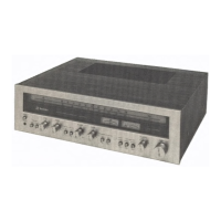
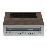
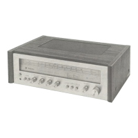
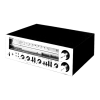
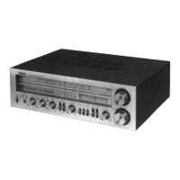
Identification and location of all front panel controls, knobs, and indicators.

Block Diagrams and Installation Guides

Overall Block Diagram

Overview of the internal circuitry and signal flow of the receiver.

Dial Cord Installation Guide

Step-by-step instructions for installing the dial cord for the tuning mechanism.

Cabinet Removal Procedure

Procedure for safely removing the unit's cabinet for servicing or access.

Service Aids and Circuitry Principles

FM Soft Muting Feature

Detailed explanation of the FM soft muting feature and its operational benefits.

Muting Circuitry Principles

Analysis of the circuit principles driving the FM muting functionality.

Alignment Instructions

Main Amplifier and Stereo Alignment

Procedures for aligning the main amplifier's IcQ and stereo separation for optimal performance.

FMAM RF, IF, and AF Circuit Alignment

Alignment procedures for the FM/AM Radio Frequency, Intermediate Frequency, and Audio Frequency amplifier circuits.

Tuning Scale and MutingPilot Alignment

Instructions for aligning the tuning scale, soft muting level, and FM MPX pilot signal.

Integrated Circuit Block Diagrams

Terminal Board and Speaker Protection Circuits

Diagrams for input/tape deck terminals and the speaker protection circuit.

Power Supply Circuit Diagram

Schematic diagram of the power supply circuit, including transformer and fuses.

Schematic Diagram

Circuit Board Layouts

FMAM Section Circuit Board Layouts

Printed circuit board layouts for FM RF, FM IF, Amplifier, and AM circuits.

Replacement Parts List - Core Components

Power Transistor Circuit Board Layout

Printed circuit board layout specifically for the power transistor section.

Speakers Terminal Circuit Board Layout

Printed circuit board layout for the speaker terminal connections.

Cabinet & Chassis Parts

Replacement Parts - Electronic Components

Capacitors and Variable Components List

Listing of all capacitors and variable resistors with their specifications.

Lamps, Fuses, and Switches List

Identification of lamps, fuses, and switches used in the receiver.

Accessories and Packing Information

Included Accessories

List of accessories supplied with the receiver, such as antenna and fuses.

Packing Materials Details

Information on packing materials used for shipping and protection of the unit.

Related product manuals