EasyManua.ls Logo

Technics SA-203

Technics SA-203
18 pages
To Next Page IconTo Next Page
Loading...
ORDER
NO.
SD82082280C2
ervice
Manual
FM/AM
Stereo
Receiver
SA-203
[EGA]
SA-203(K)
[EGA]
*
The
cabinet
and
front
panel
are
available
in
black
color
and
silver
Area
types.
*
The
black
type
model
is
provided
with
(K)
in
the
Service
Manual.
*
[EGA]
is
available
in
F.R.
Germany.
TECH
N
]
SCH
E
DATE
N
(Spezifikationen
K6nnen
infolge
von
Verbesserungen
ohne
Ankiindigung
geandert
werden.)
(DIN
45
500)
@
VERSTARKERTEIL
Gerauschabstand
Nennleistung
(4
©)
Phono
Aux,
Tape
—26
dB
Leistung
(4
Q)
Phono
Aux,
Tape
50
mW
Leistung
(4
©)
Phono
Aux,
Tape
Frequenzgang
Phono
70
dB
(nach
IHF,
A:
78
dB)
Dauerton-Ausgangsleistung
bei
20
Hz
~
20
kHz
88
dB
(nach
IHF,
A:
95
dB)
beide
Kandle
ausgesteuert
2
X
30W
(4.9)
2
X
30W
(8
Q)
Dauerton-Ausgangsleistung
bei
40
Hz
~
16
kHz
beide
Kanile
ausgesteuert
2X:
30W
(4
Q)
2
X
30W
(8
)
64
dB
66
dB
62
dB
Dauerton-Ausgangsleistung
bei
1
kHz
62
dB
beide
Kanadle
ausgesteuert
2
X
35W
(4
Q)
2
X
33W
(8
Q)
RIAA-Standardkurve
+0,8
dB
(30
Hz
~
15
kHz)
5
Hz
~
70
kHz2(
-3
dB)
+0,2
dB
(20
Hz
~
20
kHz)
GehGrrichtige
Lautstarkekorrektur
(Loudness)
(bei
-30
dB
Ausgangsleistung)
Ausgangsspannung
und
-impedanz
Tape
Aufnahme
(TAPE
REC
OUT)
Gesamtklirrfaktor
Nennleistung
bei
20
Hz
~
20
kHz
0,08%
(4
Q)
0,04%
(8
Q)
0,08%
(4
Q)
0,04%
(8
Q)
0,04%
(4
9)
0,04%
(8
Q)
0,025%
(8
Q)
Aux,
Tape
Nennleistung
bei
40
Hz
~
16
kHz
Nennleistung
bei
1
kHz
50
Hz,
+9 dB
150
mV
halbe
Nennleistung
bei
20
Hz
~
20
kHz
halbe
Nennleistung
bei
1
kHz
—26
dB
Leistung
bei
1
kHz
50
mW
Leistung
bei
1
kHz
Intermodulationsfaktor
Nennleistung
bei
250
Hz:
8
kHz
=
4:1,
4
Q
0,08%
Nennleistung
bei
60
Hz:
7
kHz
=
4:1,
nach
SMPTE,
8
Q
0,04%
0,009%
(8
1)
0,1%
(4
9)
0,12%
(4
Q)
Leistungsbandbreite
beide
Kandle
ausgesteuert
bei
—3
dB
10
Hz
~
30
kHz
(4
)
Dampfungsfaktor
15
(4.Q),
30
(8.Q)
Eingangsempfindlichkeit
und
-impedanz
Phono
2,5
mV/47
kQ
Aux
150
mV/22
kQ
Tape
180
mV/22
kQ
Maximale
TA-Eingangsspannung
(1
kHz,
eff.)
130
mV
Klangregler
Bafregler
(BASS)
Hdhenregler
(TREBLE)
‘Technics
50
Hz,
+10
dB
~
—10
dB
20
kHz,
+10
dB
~
-10
dB
+1
dB
55
dB
260
mV/330
Q
Kanalabweichung
(Aux,
250
Hz
~
6300
Hz)
Obersprechdaémpfung
(Aux,
1
kHz)
KopfhGrerpegel
und
-impedanz
Lautsprecherimpedanz
MAIN
oder
REMOTE
MAIN
und
REMOTE
4Q~169
8Q~
169
@
UKW-TUNERTEIL
Wellenbereich
87,5
~
108
MHz
Eingangsempfindlichkeit
S/R
30
dB
S/R
26
dB
S/R
20
dB
Nutzempfindlichkeit
nach
IHF
Gesamtklirrfaktor
Mono
:
:
0,15%
Stereo
0,2%
1,3
pV
(75.9)
1,2
pV
(75
Q)
0,9
pV
(75
Q)
1,5
pV
(nach
IHF
’58)
Matsushita
Electric
Trading
Co.,
Ltd.
P.O.
Box
288,
Central
Osaka
Japan
Question and Answer IconNeed help?

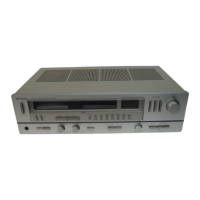
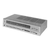
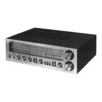
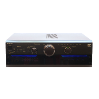
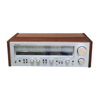
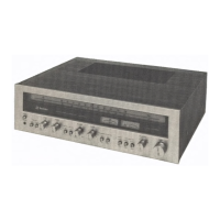
Do you have a question about the Technics SA-203 and is the answer not in the manual?

Technics SA-203 Specifications

General IconGeneral
Frequency Response20Hz to 20kHz
Input Sensitivity2.5mV (MM), 150mV (line)
Tuning rangeFM, MW
Total Harmonic Distortion0.04%
Speaker load impedance8 ohms

Summary

Technical Data

Amplifier Specifications

Detailed technical specifications for the amplifier section.

FM Tuner Specifications

Detailed technical specifications for the FM tuner section.

Location of Controls

Technical Guide

Power Switch Muting Operation

Explains muting during power on and off for shock noise prevention.

Speaker Short Protection Circuit

Details the protection circuit's response to speaker terminal short circuits.

Disassembly Instructions

Cabinet Removal Procedure

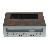
Step-by-step guide to detach the main cabinet housing.

Front Panel Removal

Instructions for safely removing the front panel assembly.

Dial Scale Detachment

Procedure to detach the dial scale from the unit.

Peak Power Indicator PCB Removal

Steps to remove the printed circuit board for peak power indicators.

Power Amplifier IC Removal

Detailed instructions for removing the main power amplifier integrated circuit.

Measurements and Adjustments

FM Offset Voltage Adjustment

Procedure for adjusting the FM offset voltage setting.

FM Discriminator Alignment

Steps to align the FM discriminator circuit for optimal performance.

FM Muting Level Adjustment

Procedure for adjusting the FM muting sensitivity level.

AMFM Alignment Procedures

Comprehensive guides for aligning AM and FM sections.

FM IF Alignment Steps

Specific alignment steps for the FM Intermediate Frequency circuit.

FM Stereo Decoder Alignment

Procedures for aligning the FM stereo decoder for accurate stereo signals.

FM Muting Sensitivity Adjustment

How to adjust the FM muting sensitivity level.

Dial Cord Installation Guide

Instructions for correctly installing the dial cord mechanism.

Block Diagram

Circuit Board and Wiring Diagram

Schematic Diagram

Differential Circuit Schematic

Detailed schematic of the differential amplifier section.

Power Amplifier Circuit Schematic

Schematic of the main power amplifier stage.

Power Supply Circuit Schematic

Schematic of the unit's power supply section.

Exploded View

Replacement Parts List

Related product manuals