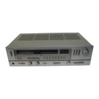
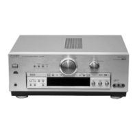
The Technics SA-222 is an FM/AM Stereo Receiver, available in the USA ([M]) and Canada ([MC]), with additional versions ([PA], [PE]) for East PX and European Military markets, respectively. This service manual provides comprehensive details for its operation, maintenance, and repair.
Function Description
The SA-222 functions as a central audio component, integrating an amplifier and an FM/AM tuner. It is designed to receive radio broadcasts and amplify audio signals from various input sources, delivering them to speakers or headphones. The receiver features both analog and digital frequency displays, preset tuning capabilities, and a range of controls for sound customization.
Important Technical Specifications
Amplifier Section (IHF '78)
- Rated Minimum Sine Wave RMS Power Output: 30W per channel into 8 ohms, 20 Hz–20 kHz, with 0.04% total harmonic distortion.
- 1 kHz Continuous Power Output: 33W per channel into 8 ohms, 0.04% total harmonic distortion; 35W per channel into 4 ohms.
- Dynamic Headroom: 0.7 dB (8 ohms).
- Total Harmonic Distortion:
- Rated power (20 Hz–20 kHz): 0.04% (8 ohms).
- Half power (20 Hz–20 kHz): 0.025% (8 ohms).
- Half power (1 kHz): 0.009% (8 ohms).
- SMPTE Intermodulation Distortion: 0.04% (8 ohms).
- Frequency Response:
- PHONO: RIAA standard curve ±0.8 dB.
- TUNER, AUX, TAPE: 5 Hz–70 kHz, -3 dB; 20 Hz–20 kHz, +0.2 dB, -0.2 dB.
- Input Sensitivity:
- PHONO: 0.5 mV (2.5 mV, IHF '66).
- TAPE: 30 mV (150 mV, IHF '66).
- S/N (IHF, A):
- PHONO: 75 dB (80 dB, IHF '66).
- TUNER, AUX, TAPE: 80 dB (95 dB, IHF '66).
- Maximum Input Voltage (PHONO): 120 mV (130 mV, 1 kHz).
- Input Impedance:
- PHONO: 47 kilohms.
- TAPE: 22 kilohms.
- Tone Controls:
- BASS: 50 Hz, +10 dB to -10 dB.
- TREBLE: 20 kHz, +10 dB to -10 dB.
- Subsonic Filter: 30 Hz, 6 dB/oct.
- Loudness Control (volume at -30 dB): 50 Hz, +9 dB.
- Low Frequency Damping Factor: 30 (8 ohms), 15 (4 ohms).
- Load Impedance:
- MAIN or REMOTE: 4–16 ohms.
- MAIN and REMOTE: 8–16 ohms.
FM Tuner Section
- Frequency Range: 87.9–107.9 MHz (standard setting). Note: If the FM/AM allocation selector is set to "FM 0.05 MHz/AM 9 kHz," the range becomes 87.50–108.00 MHz.
- Sensitivity: 10.8 dBf (1.9 µV, IHF '58).
- 50 dB Quieting Sensitivity:
- MONO: 13.7 dBf (2.7 µV, IHF '58).
- STEREO: 37.2 dBf (39.7 µV, IHF '58).
- Total Harmonic Distortion:
- 100 Hz: 0.15% (MONO), 0.2% (STEREO).
- 1 kHz: 0.15% (MONO), 0.2% (STEREO).
- 6 kHz: 0.3% (MONO), 0.3% (STEREO).
- S/N:
- MONO: 75 dB.
- STEREO: 70 dB.
- Frequency Response: 20 Hz–15 kHz, +1 dB, -2 dB.
- Alternate Channel Selectivity: 70 dB.
- Capture Ratio: 1.2 dB.
- Image Rejection (98 MHz): 55 dB.
- IF Rejection (98 MHz): 75 dB.
- Spurious Response Rejection (98 MHz): 82 dB.
- AM Suppression: 55 dB.
- Stereo Separation:
- 1 kHz: 42 dB.
- 10 kHz: 32 dB.
- Carrier Leak:
- 19 kHz: -38 dB.
- 38 kHz: -50 dB.
- Antenna Terminals: 300 ohms (balanced), 75 ohms (unbalanced).
AM Tuner Section
- Frequency Range: 530–1620 kHz (standard setting). Note: If the FM/AM allocation selector is set to "FM 0.05 MHz/AM 9 kHz," the range becomes 522–1611 kHz.
- Sensitivity: 30 µV, 300 µV/m.
- Selectivity: 55 dB.
- Image Rejection (1000 kHz): 50 dB.
- IF Rejection (1000 kHz): 40 dB.
General
- Power Consumption: 185W.
- Power Supply: AC 120V, 60 Hz.
- Dimensions (WxHxD): 430 x 120 x 300 mm (16-15/16" x 4-23/32" x 11-13/16").
- Weight: 5.9 kg (13 lb.).
Usage Features
The SA-222 offers a user-friendly interface with a range of controls for an optimal listening experience.
- Input Selectors: Dedicated buttons for AUX, TUNER, and PHONO inputs, allowing easy switching between audio sources.
- Tape Monitor Selectors: Separate controls for TAPE 1 and TAPE 2, enabling monitoring of recordings or connecting additional audio devices.
- Volume Control: A large rotary knob for precise adjustment of overall output volume.
- Tone Controls: Rotary knobs for BASS and TREBLE, allowing users to customize the low and high-frequency response.
- Balance Control: A rotary knob to adjust the left/right channel balance.
- Loudness Control: A switch to activate a loudness contour, enhancing bass and treble at low listening levels.
- Subsonic Filter: A switch to engage a filter that reduces unwanted very low-frequency noise.
- FM Muting/FM Mode: A switch with "on/FM auto" and "off/FM mono" settings, allowing for noise reduction during FM reception and selection of stereo or mono playback.
- Band Selectors: Buttons for AM and FM radio bands.
- Tuning Controls: Up and down buttons for manual tuning, complemented by an analog frequency meter and a digital frequency meter for precise station selection.
- Preset Tuning: Multiple preset buttons (1-7) for storing and recalling favorite radio stations.
- Automatic Scan: A switch to enable automatic scanning for radio stations.
- Quartz-Lock Indicator: An indicator light confirming stable tuning.
- FM Stereo Indicator: An indicator light for FM stereo broadcasts.
- Memory Indicator: An indicator light for preset memory functions.
- Signal-Strength Indicators: LED indicators to show the strength of the received radio signal.
- Speaker Selectors: Switches for MAIN and REMOTE speaker outputs, allowing users to select which set of speakers is active.
- Headphones Jack: A front-panel jack for private listening.
- Rear Panel Connectivity: Includes AM antenna terminals (ferrite-bar and external), FM antenna terminals (300Ω and 75Ω), Phono input, Aux input, Tape 1 and Tape 2 (Rec out/Playback) connections, and unswitched AC outlets.
- FM/AM Allocation Selector: A rear-panel switch to select between different frequency steps (0.2MHz/10kHz or 0.05MHz/9kHz), accommodating regional broadcasting standards.
- Battery (Memory Reserve): An internal battery for retaining preset memory settings.
Maintenance Features
The service manual provides detailed instructions for disassembly, adjustment, and replacement of components, facilitating efficient maintenance and repair.
- Cabinet Removal: Step-by-step guide for removing the top cabinet and bottom board, providing access to internal components.
- Front Panel and Meter Removal: Instructions for detaching the front panel, FM/AM preset tuning printed circuit board, and analog frequency meter.
- Power IC Removal: Detailed procedure for safely removing and remounting the power IC, including the application of silicone compound for heat dissipation.
- Chip Replacement: Specific guidelines for replacing chip resistors, capacitors, and jumpers, emphasizing proper soldering techniques (using solder sucker, tweezers, and a low-wattage soldering iron) and precautions against overheating or damaging electrodes.
- Adjusting Instructions: Comprehensive procedures for AM and FM tuner adjustments, including:
- AM-IF Adjustment: Tuning the 1st IFT (T201) for maximum output.
- Analog Frequency Meter Adjustment: Calibrating the frequency meter using L4 (FM OSC Coil), CT1 (FM OSC Trimmer), and VR102 (Frequency meter) for accurate display at specific frequencies (90.1MHz, 106.1MHz, 100.1MHz, 107.9MHz).
- AM-RF Adjustment: Adjusting CT202 (AM OSC Trimmer) and L202 (AM OSC Coil) for accurate frequency meter indication and proper range.
- FM-IF Adjustment: Adjusting T101 (Discri. IFT) for 0V signal mode voltage.
- FM RF Adjustment: Tuning L1 (FM ANT Coil), L2 (FM DET Coil), and T1 (FM IFT) for symmetrical output waveform and maximum output.
- FM Muting Level Adjustment: Adjusting VR101 (Muting level) to release muting under specified conditions.
- FM MPX Pilot (VCO) Adjustment: Adjusting VR301 (VCO) for 19kHz ± 30Hz carrier leak.
- Stereo Distortion Adjustment: Fine-tuning T1 (IFT) to minimize distortion in the L channel.
- Printed Circuit Board Layouts: Detailed diagrams of the Tuner circuit & Equalizer circuit, FM/AM preset tuning circuit, Main amplifier circuit, and Stereo eye driver circuit, indicating component locations and signal paths.
- Schematic Diagrams: Full schematic diagrams with voltage values, signal lines, and switch functions, crucial for troubleshooting and understanding circuit operation.
- Replacement Parts Lists: Extensive lists of electrical and cabinet/chassis parts, including part numbers, descriptions, and quantities, with specific notes for safety-critical components and regional variations.
- Safety Notice: Highlighted shaded areas in schematic diagrams indicate special features important for safety, requiring manufacturer-specified parts for replacement.
- Troubleshooting Precautions: Advice for checking FL (display tube), FL driver, digit circuit, and micro-computer with an oscilloscope, emphasizing care to avoid short circuits or applying incorrect voltage to IC terminals.
- Shorting Switch Description: Explanation of how shorting switches (S401, S402, S403, S406, S407) function in the unit, where a common terminal is shorted to the next circuit.