EasyManua.ls Logo

Technics SA-222 M

Technics SA-222 M
21 pages
To Next Page IconTo Next Page
Loading...
ORDER
NO.
§D8012-1811
ervice
Manual
FM/AM
Stereo
Receiver
SA-222
[M],
[MC]
Areas
*
[M]
is
available
in
U.S.A.
*
[MC]
is
available
in
Canada.
TECHNICAL
SPECIFICATIONS
_
Specifications
are
subject
to
change
without
notice
for
further
improvement.
I
}
Subsonic
filter
30
Hz,
—6
dB/oct.
(
He
78)
Loudness
control
(volume
at
—30
dB)
50
Hz,
+9
dB
@
AMPLIFIER
SECTION
Low
frequency
damping
factor
30
(8
ohms)
15
(4
ohms)
eat
<
Load
impedance
Rated
minimum
sine
wave
RMS
power
output
MAIN
or
REMOTE
4246
Shine
20
Hz~20
kHz
both
channels
driven
MAIN
and
REMOTE
8~16
ohms
0.04%
total
harmonic
distortion
30W
per
channel
(8
ohms)
@
FM
TUNER
SECTION
1
kHz
continuous
power
output
both
channels
driven
Frequency
range
87.9~
107.9
MHz
0.04%
total
harmonic
distortion
Sensitivity
10.8
dBf
(1.9
uV,
IHF
'58)
33W
per
channel
(8
ohms)
50
dB
quieting
sensitivity
35W
per
channel
(4
ohms)
MONO
13.7
dBf
(2.7
uV
IHF
'58)
Dynamic
headroom
0.7
dB
(8
ohms)
STEREO
37.2
dBf
(39.7
uV
IHF
'58)
Total
harmonic
distortion
Total
harmonic
distortion
rated
power
at
20
Hz~20
kHz
0.04%
(8
ohms)
100
Hz
0.15%
(MONO),
0.2%
(STEREO)
half
power
at
20
Hz~20
kHz
0.025%
(8
ohms)
1
kHz
0.15%
(MONO),
0.2%
(STEREO)
half
power
at
1
kHz
0.009%
(8
ohms)
6
kHz
0.3%
(MONO),
0.3%
(STEREO)
SMPTE
intermodulation
distortion
0.04%
(8
ohms)
S/N
PHONO
RIAA
standard
curve
+0.8
dB
MONO
75
dB
TUNER,
AUX,
TAPE
5
Hz~70
kHz,
—3
dB
STEREO
70
dB
20
Hz~20
kHz,
+0.2
dB,
—0.2
dB
Frequency
response
20
Hz~15
kHz,
+1
dB
—2
dB
Input
sensitivity
Alternate
channel
selectivity
70
dB
PHONO
0.5
mV
(2.5
mV,
IHF
'66)
Capture
ratio
4.2dB
TAPE
30
mV
(150
mV,
IHF
'66)
image
rejection
at
98
MHz
55
dB
S/N
(IHF,
A)
IF
rejection
at
98
MHz
75
dB
PHONO
75
dB
(80
dB,
IHF
’66)
Spurious
response
rejection
at
98
MHz
82 dB
TUNER,
AUX,
TAPE
80
dB
(95
dB, IHF
'66)
AM
suppression
55
dB
Maximum
input
voltage
Stereo
separation
PHONO
120
mV
(130
mV,
1
kHz)
1
kHz
42
dB
Input
impedance
10
kHz
32
dB
PHONO
47
kilohms
Carrier
leak
TAPE
22
kilohms
19
kHz
~38
dB
Tone
controls
38
kHz
~60
dB
BASS
50
Hz,
+10
dB~
-10
dB
Antenna
terminals
300
ohms
(balamced)
TREBLE
20
kHz,
+10
dB~
-10
dB
75
ohms
(unbaamced)
Panasonic
Company
Panasonic
Hawaii,
Inc.
Panasonic
Canada
Ti
nh
=
Division
of
Matsushita
Electric
320
Waiakamilo
Road,
Honolulu,
Division
of
Matsushita
Electric,
ec
nics
Corporation
of
America
Hawaii
96817
of
Canada
Ltd.
One
Panasonic
Way,
Secaucus,
5770
Ambler
Drive,
New
Jersey
07094
Mississauga,
Ontario
L4W
2T3
Question and Answer IconNeed help?

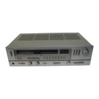
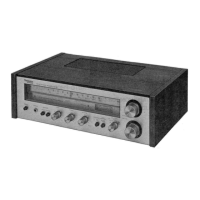
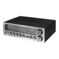
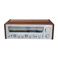
Do you have a question about the Technics SA-222 M and is the answer not in the manual?

Technics SA-222 M Specifications

General IconGeneral
Power output30 watts per channel into 8Ω (stereo)
Total harmonic distortion0.04%
Input sensitivity2.5mV (MM), 150mV (line)
Dimensions430 x 142 x 276mm
Weight6.4kg

Summary

Technical Specifications

Amplifier Section Specifications

Detailed specifications for the amplifier stage, including power output and distortion.

FM Tuner Section Specifications

Detailed specifications for the FM tuner, including sensitivity and frequency range.

Disassembly Instructions

How to Remove the Cabinet

Step-by-step guide for removing the outer cabinet of the unit.

How to Remove the Bottom Board

Instructions for detaching the bottom panel of the receiver.

How to Remove Tuning Circuit Board and Frequency Meter

Procedure for removing specific internal components like the tuning board and meter.

How to Remove the Power IC

Detailed steps for safely removing and replacing the power integrated circuit.

How to Replace Chips (Resistors, Capacitors, Jumpers)

Guidance on desoldering and soldering small electronic components like chips.

Adjustment Procedures

AM Tuner, IF, RF, and Frequency Meter Adjustments

Procedures for calibrating AM tuner, IF, RF, and frequency meter sections.

FM Tuner, IF, RF, Muting, MPX Pilot, and Stereo Distortion Adjustments

Procedures for calibrating FM tuner, IF, RF, muting, MPX pilot, and stereo distortion.

Adjustment Points Overview

Block Diagram Overview

Electric Parts Replacement List

Printed Circuit Board Layouts

Tuner, Equalizer, and Stereo Eye Driver PCBs

Diagrams showing the layout of tuner, equalizer, and stereo eye driver circuit boards.

FMAM Preset Tuning Circuit Board Layout

Diagram showing the layout of the FM/AM preset tuning circuit board.

Schematic Diagram

Exploded Views

Cabinet and Chassis Parts List

Replacement Parts List (Component Changes)

Schematic Diagram Changes

Power Source and RECPLAY Circuit Modifications

Details on modifications to the power source and record/playback circuit schematics.

Related product manuals