EasyManua.ls Logo

Technics SA-310

Technics SA-310
45 pages
To Next Page IconTo Next Page
Loading...
ORDER NO. MD9707082C2
Receiver
AV Control Stereo Receiver
Colour
(K) . . . . . . . . Black Type
SA-EX310
© 1997 Matsushita Electronics (S) Pte. Ltd.
All rights reserved. Unauthorized copying and
distribution is a violation of law.
Area
®
Manufactured under license from Dolby Laboratories Licensing Corporation. Additionally licensed
under one or more of the following patents: U.S. numbers 3,632,886,3,746,792 and 3,959,590;
Canadian numbers 1,004,603 and 1,037,877.
"Dolby" and the double-D symbol are trade marks of Dolby Laboratories Licensing Corporation.
*
Colour
Area
Suffix for
Model No.
(E) Europe
(EB) Great Britain
(EG) Germany and Italy
(K)
SPECIFICATIONS\ ÒÅÕÍÈ×ÅÑÊÈÅ ÕÀÐÀÊÒÅÐÈÑÒÈÊÈ
PROTECTION CIRCUITRY\ ÑÈÑÒÅÌÀ ÇÀÙÈÒÛ
CAUTION FOR AC MAIN LEADS\ ÌÅÐÛ ÁÅÇÎÏÀÑÍÎÑÒÈ ÏÐÈ ÐÀÁÎÒÅ ÑÎ ØÍÓÐÎÌ
ÏÈÒÀÍÈß ÏÅÐÅÌÅÍÍÎÃÎ ÒÎÊÀ
OPERATION CHECKS AND MAIN COMPONENT REPLACEMENT
PROCEDURES\ÏÐÎÂÅÐÊÀ ÐÀÁÎÒÎÑÏÎÑÎÁÍÎÑÒÈ È ÇÀÌÅÍÀ ÎÑÍÎÂÍÛÕ
ÊÎÌÏÎÍÅÍÒÎÂ
FAN MOTOR TROUBLESHOOTING\ ÍÅÈÑÏÐÀÂÍÎÑÒÈ ÄÂÈÃÀÒÅËß ÎÕËÀÆÄÅÍÈß
TROUBLESHOOTING\ ÍÅÈÑÏÐÀÂÍÎÑÒÈ È ÌÅÒÎÄÛ ÈÕ ÓÑÒÐÀÍÅÍÈß
BLOCK DIAGRAM\ ÁËÎÊ-ÑÕÅÌÀ
TERMINAL FUNCTIONS OF IC's\ ÔÓÍÊÖÈÎÍÀËÜÍÎÅ ÍÀÇÍÀ×ÅÍÈÅ ÂÛÂÎÄÎÂ
ÈÍÒÅÃÐÀËÜÍÛÕ ÌÈÊÐÎÑÕÅÌ
TERMINAL GUIDE OF IC's, TRANSISTORS & DIODES\ ÖÎÊÎËÅÂÊÀ ÂÛÂÎÄÎÂ
ÈÍÒÅÃÐÀËÜÍÛÕ ÌÈÊÐÎÑÕÅÌ, ÒÐÀÍÇÈÑÒÎÐÎÂ È ÄÈÎÄÎÂ
SCHEMATIC DIAGRAMS\ ÏÐÈÍÖÈÏÈÀËÜÍÛÅ ÑÕÅÌÛ
PRINTED CIRCUIT BOARDS\ ÏÅ×ÀÒÍÛÅ ÏËÀÒÛ
WIRING CONNECTION DIAGRAM\ ÑÕÅÌÀ ÑÎÅÄÈÍÅÍÈß
CABINET PARTS LOCATION\ ÐÀÑÏÎËÎÆÅÍÈÅ ×ÀÑÒÅÉ ÊÎÐÏÓÑÀ
REPLACEMENT PARTS LIST\ ÑÏÈÑÎÊ ÇÀÏÀÑÍÛÕ ×ÀÑÒÅÉ
RESISTORS & CAPACITORS\ ÐÅÇÈÑÒÎÐÛ È ÊÎÍÄÅÍÑÀÒÎÐÛ
PACKAGING\ÓÏÀÊÎÂÊÀ
Question and Answer IconNeed help?

Do you have a question about the Technics SA-310 and is the answer not in the manual?

Technics SA-310 Specifications

General IconGeneral
BrandTechnics
ModelSA-310
CategoryStereo Receiver
LanguageEnglish

Summary

Specifications

Protection Circuitry

Protection Circuitry Function

Explains how the protection circuitry works and when it may activate.

Troubleshooting Protection Circuit

Steps to take if the protection circuit activates.

Caution for AC Main Leads

Safety Precautions for AC Power

Important safety information regarding the AC power cord and plug.

Fuse Replacement Procedure

Step-by-step guide for replacing the fuse in the plug.

Operation Checks and Main Component Replacement Procedures

Checking Procedures for Major P.C.B.

Steps for checking operations on various printed circuit boards.

Power IC and Regulator Transistor Replacement

Detailed steps for replacing the power IC and regulator transistor.

Fan Motor Troubleshooting

Fan Motor Error Detection

Explains the fan motor error sensing and "OVER LOAD" display.

Fan Motor Circuit Check

Steps and diagrams for checking the fan motor and its driving circuit.

Troubleshooting

Troubleshooting Test Points

Identifies test points on circuit boards for troubleshooting.

Amplifier Circuit Waveform Analysis

Compares normal and faulty waveforms for amplifier circuit troubleshooting.

Surround Circuit Checking Procedure

Procedure to test the surround circuit using a service mode.

Overload Detection Functionality

Explains the overload detection mechanism and how to respond to it.

Block Diagram

Terminal Functions Of ICs

IC901 Microprocessor Terminal Functions

Detailed pin functions for the M38B53M4053F microprocessor.

Terminal Guide of ICs, Transistors and Diodes

Pin configurations for various ICs, transistors, and diodes.

Schematic Diagram

Tuner Circuit Schematic

Detailed schematic of the FM/AM tuner circuit.

Pro Logic Decoder Schematic

Detailed schematic of the Pro Logic decoder circuit.

Replacement Parts List

Resistors

List of replacement resistors with values.

Resistors (Continued)

Continuation of the replacement resistors list with values.

Capacitors

List of replacement capacitors with values.

Capacitors (Continued)

Continuation of the replacement capacitors list with values.
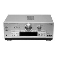
Related product manuals