ORDER
NO.
SD83012363C8
Service
Manual
eb
5.-
'W,!
ooe.r
tB
f
H>( 000, f i«>
iiü.<;<i>|6!
i,
"•.b
G.:
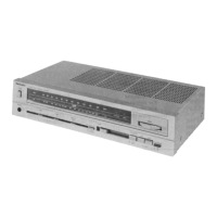
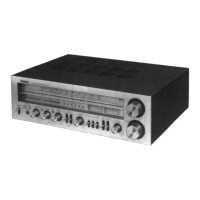
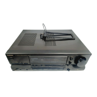
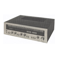
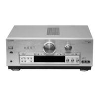
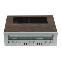
FM/AM
Stereo
Receiver
SA-110
[EX],[EH],[XA],[XL]
SA-110
(K)
[EX],[EH]
Areas
*
The colors of this model included silver and black.
*
The black type model is provided
with
(K) in the
Service
Manual.
*
[EX] is available in Switzerland and
Scandinavia.
*
[EH] is available in Holland.
*
[XAl is available in Southeast
Asia,
Oceania,
Africa,
Middle
Near
East
and Central South America.
*
[XL] is available in Australia.
Specifications
(Specifications
are subject to change
without
notice for
further
improvement.)
(DIN 45 500) ; s/N
rated power (40)
•
AMPLIFIER
SECTION
PHONO
TAPE/AUX
70
dB (IHF, A: 73 dB)
88
dB (IHF, A: 95 dB)
40
Hz~20
kHz continuous power
output
-26 dB power (40)
both
channels driven
2
X 20W (40)
PHONO
64
dB
2
X 20W (80)
TAPE/AUX
66
dB
40 Hz~16 kHz continuous power
output
50 mW power (40)
both
channels driven
2
X 20W (40)
PHONO
62
dB
2
X 20W (80)
TAPE/AUX
62
dB
1
kHz continuous power
output
^ , ,
Tone
Controls
both
channels driven
2
X 20W (40)
BASS
50
Hz, +10 dB- -10 dB
'ii-.j.iini
er»nu
2
X 20W (80)
TREBLE
20
kHz, +10 dB- -10 dB
Total harmonie distortlon
Loudness
control
(built
in)
rated power at 40
Hz~20
kHz
0.8%
(40)
0.5%
(80)
volume at -30 dB
Output voltage and impedance
50
Hz, +5 dB
rafed power at 40 Hz~16 kHz
0.8%
(40)
TAPE
REC OUT
150
mV
0.5%
(80)
Channel
balance,
TAPE/AUX
250
Hz~6,300
Hz +1 dB
rated power at 1 kHz
0.5%
(40)
Channel
separation,
TAPE/AUX
1 kHz 55 dB
0.5%
(80)
Headphones
output
level and impedance 390 mV/330O
half power at 1 kHz
0.07%
(80)
Load
impedance
40~160
26 dB power at 1 kHz
50 mW power at 1 kHz
0.1%
(40)
0.12%
(40)
•
FM
TUNER
SECTION
Intermodulation distortlon
Frequency
range
87.5-108.0
MHz
rated power at 250 Hz: 8 kHz=4:1, 40
0.8%
Sensitivlty
rated power at 60 Hz: 7 kHz=4:1,
SMPTE,
80 0.5%
S/N 30 dB
1.9 yuV
(300O),
1.3/iV (750)
Power
bandwidth
S/N 26 dB
A.7
fjV
(300O),
1.2/yV (750)
both
channels driven, -3 dB
10
Hz~30 kHz (40)
S/N 20 dB
1.5/yV
(300O),
0.9 yuV (750)
Damping factor
15
(40), 30 (80)
IHF usable sensitivlty
1.9 fiV (IHF '58)
Input
sensitivlty and impedance
IHF 46 dB stereo quieting sensitivlty 22 üV/750
PHONO
O,.
.,n- i
2.5
mV/47kO
Total harmonie distortlon
TAPE/AUX
150
mV/18kO
MONO
0.15%
PHONO maximum input voltage (1 kHz, RMS) 130 mV
STEREO
0.3%
Frequency
response
S/N
PHONO
RIAA
Standard curve
MONO
60
dB (76 dB, IHF)
+0.8
dB
(30 Hz~15 kHz)
STEREO
58
dB (70 dB, IHF)
TAPE/AUX
(at vol. max.) 5 Hz~70 kHz (-3 dB)
Frequency
response
20
Hz-15 kHz, +1 dB- -2 dB
Technics
Matsushita
Electric
Trading Co., Ltd.
P.O.
Box 288,
Central
Osaka
Japan