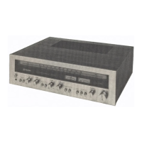
SA-110
8Ti4zyxwvutsrqponmlkjihgfedcbaZYXWVUTSRQPONMLKJIHGFEDCBA,3MïeUiaA
QUA 8TM3.
•
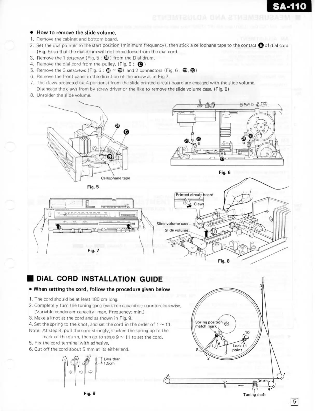
How to remove the
slide
volume.
1.
Remove the cabinet and
bottom
board.
2.
Set the dial pointer to the start position (minimum frequency), then stick a cellophane tape to the contact ©o^ dial cord
(Fig.
5) so that the dial drum will not come loose from the dial cord.
3.
Remove the
1
setscrew
(Fig.
5 :©) from the Dial drum. , . .
4.
Remove the dial cord from the pulley. (Fig. 5 : 0)
5.
Remove the 3
setscrews
(Fig. 6 : © ®) and 2 connectors (Fig. 6 : ©, ®)
6.
Remove the
front
panel in the direction of the arrowas in Fig 7.
7.
The
claws
projected (at 4 portions) from the slide printed circuit board are engaged with the slide volume. , • ,. , .
Disengage
the
claws
from by
screw
driver or the like to remove the slide volume
case.
(Fig. 8)
8.
Unsolder the slide volume.
#1^,
•
i,
Fig.
6
Cellophane
tape
Fig.
5
-
— —
-
- _
-
1
1
11
•'|i'iiiroiiii,i-iiiiiiiizyxwvutsrqponmlkjihgfedcbaZYXWVUTSRQPONMLKJIHGFEDCBA 1
Fig.
7
Slide
volume
case.^
Slide
volume
•
DIAL
CORD
INSTALLATION GUIDE
•
When setting the
cord,
follow the procedure given below
1.
The cord should be at least 180 cm long.
2.
Completely
turn
the tuning gang (variable capacitor) counterclockwise
(Variable
condenser capacity: max. Frequency; min.)
3.
Make a knot at the cord and as shown in Fig. 9.
4.
Set the spring to the knot, and set the cord in the order of 1 ~ 11.
Note: At step 8, puil the cord strongly,
slacken
the spring up to the
mark
of the durm, then go to steps 9 ~ 11 to set the cord.
5.
Fix the cord terminal with
adhesive.
6.
Cut off the cord about 5 mm at its either end.
Less
than
1.5cm
Fig.
9
Tuning
shaft