SA-110
aidOfTOUflT8Hi
YJaM^ai
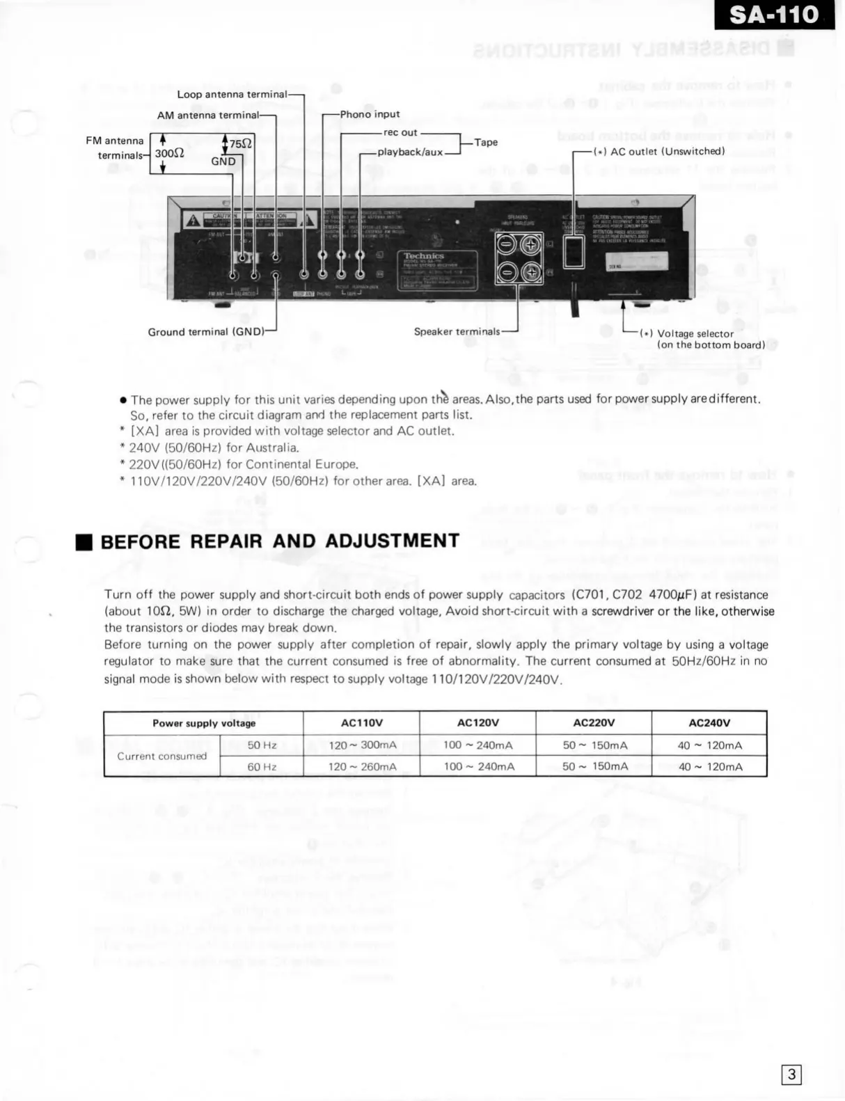
Loop antenna terminal—|
AM antenna terminal
FM
antenna
terminals- 300f2
O-
Ground terminal
(GND)—'
tsfridBO ^rh gvoms-ï ot woH •
)
AC
outlet
(Unswitched)
Speaker
terminals-
•
)
Voltage selector
(on the
bottom
board)
* The power supply for this
unit
varies
depending
upon
th"^
areas.
Also,the parts used for power supply are different.
So,
refer to the circuit diagram and the replacement parts list.
* [XA]
area
is provided
with
voltage selector and AC
outlet.
* 240V (50/60HZ) for Australië.
* 220V((50/60Hz) for Continental
Europa.
''
* 110V/120V/220V/240V (50/60Hz) for other
area.
[XA]
area.
^'^"'^^ ^"-^'^
"V"^"'''
°' "^"^^^
BEFORE
REPAIR
AND ADJUSTMENT
Turn
off the power supply and short-circuit
both
ends of power supply capacitors
(C701,
C702
4700juF)
at resistance
(about lOrZ, 5W) in order to discharge the charged voltage, Avoid short-circuit
with
a screwdriver or the like,
otherwise
the transistors or diodes may break down.
Before
turning
on the power supply after completion of repair, slowly apply the primary voltage by using a voltage
regulator to make sure
that
the current consumed is free of abnormality. The current consumed at 50Hz/60Hz in no
signal mode is shown below
with
respect to supply voltage 110/120V/220V/240V.
Power supply voltage
AC110V AC120V AC220V
AC240V
Current consumed
50
Hz
120~
300mA
100
~ 240mA
50-
150mA
40
~ 120mA
Current consumed
60
Hz
120
~ 260mA
100
~ 240mA
50
~ 150mA
40
~ 120mA
ï
r
3