Do you have a question about the Technics SA-G76 and is the answer not in the manual?
Details of the FM tuner's frequency range, sensitivity, and distortion.
Technical specifications for the amplifier's power output and distortion.
Specifications for the AM tuner, including frequency range and sensitivity.
General warning regarding servicing by experienced technicians only.
Step-by-step guide for checking major printed circuit boards.
Instructions for connecting test equipment for troubleshooting.
Procedure for testing the amplifier circuit using test equipment.
Reference waveforms for amplifier circuits and identification of faulty blocks.
Procedure for testing the surround circuit's functionality.
Explanation of the overload detection and protection circuit.
Layout and component identification for the Pro Logic PCB.
Layout and component identification for the Volume PCB.
Layout and component identification for the Panel PCB.
Layout and component identification for the Headphone Jack PCB.
Layout and component identification for the Operation PCB.
Layout and component identification for the Main PCB.
Layout and component identification for the Tuner PCB.
Layout and component identification for the Input/Output Terminal PCB.
Layout and component identification for the Tuner Pack PCB.
Layout and component identification for the Power Supply PCB.
Safety notice regarding component characteristics and replacement.
Safety notice regarding components with special characteristics.
List of coils and transformers used in the unit.
List of component combinations and their part numbers.
List of ceramic filters with their part numbers and values.
List of oscillators, including ceramic and crystal types.
Safety notice regarding component specifications and handling.
List of resistors with their part numbers, values, and ratings.
List of capacitors with their part numbers, values, and voltage ratings.
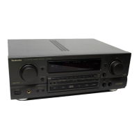
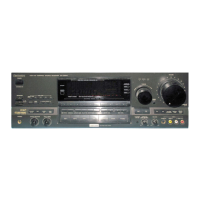
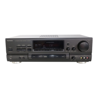
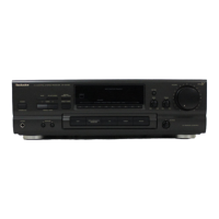
| Brand | Technics |
|---|---|
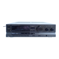
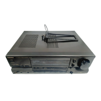
| Model | SA-G76 |
| Category | Stereo Receiver |
| Language | English |